You're reading the documentation for a development version. For the latest released version, please have a look at master.
Depth Mod Finder
Pipeline Overview
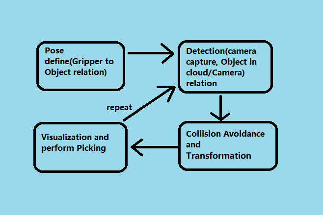
For general picking pipelines, camera & robot work together to see and pick. Vision is a software layer to communicate between all these hardwares. The stages above are essential for all the required relations in this calculation. Therefore, even if the requirements are different from project to project, the core calculation is similar.
The Depth Mod Finder pipeline has 4 stages:
Teach Pose: Teach/demonstrate the picking pose to robot;
Detection: Detect the object location in scene;
Pose Transformation (Picking flowchart): Transform all the poses and relations for picking procedure;
Picking: Robot communication and actual picking;
Teach Pose
Teach Pose is a stage for you to show the robot: how to pick the object. It has 2 kinds of teach pose, mainly differ from whether or not the robot is involved. For Mod Finder templates, we use the teach pose which the robot is involved.
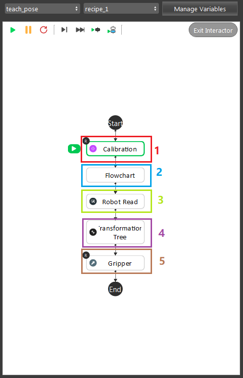
The image shown above is the example of typical teach pose procedures. It is essential for robot to know how to approach its gripper to object. This stage is required which it calculates the Object in Tool relation.
You can split this pipeline into 5 major parts:
Calibration node, load in the calibration result from local
.ymlfile. You can checkout these articles for Calibration node and Sphere Calibration node. And details of calibration procedures are Board Calibration and Sphere Calibration.Detection flowchart is executed here to find out the current Object in Cloud relation. When you execute this flowchart for the first time, you will need to define the model. You can check DA Alignment section for instructions of defining the model.
Robot Read node is reading in the robot current pose, Tool in Base relation.
Transformation Tree node collects all the relations and generate the Tool in Object pose for Gripper node.
Detection
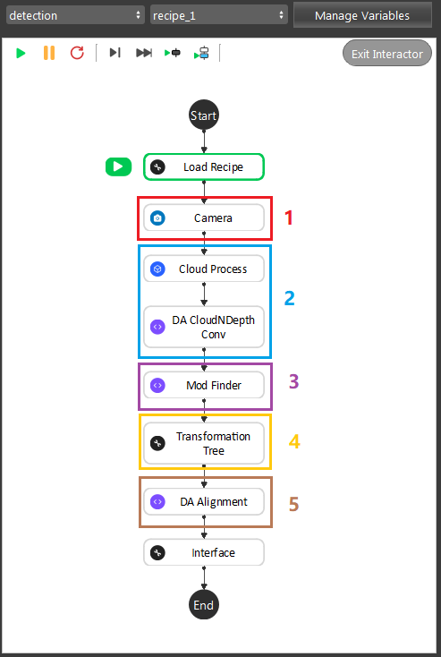
As the image above shows, the Gray Mod Finder contains 5 sections in the whole flow:
Section 1: Used the camera to capture 3D data.
Section 2: Use cloud process (adjust bounding box feature) to set the working cell of the project, and parse the cloud into depth(8-bit).
Section 3: Used mod finder 3D mode to find the object in the 8-bit depth map.
Section 4: Perform the inverse operation on the model cloud in order to align the model cloud with scene cloud.
Section 5: The alignment in this section was used to align the 3D model into the 3D space. Mod Finder node outputs the initial pose of the object here.
During the runtime, the execution flow is section 1 -> 2 -> 3 -> 5. And during the defining time, the execution flow is section 1 ->2 -> 3 -> 4 -> 5. After defining the model, as long as you do not redefine the model again, DA Alignment node will not update the pose from Section 4. Therefore, when performing picking procedure, you do not need to worry about Section 4.
Tip
You can also learn about the main ideas behind the depth mod finder engine by watching this video tutorial. (TODO, record a video)
Teach model from camera
Teaching an object model is important step when setting up the DaoAI Mod Finder engine to detect objects. Mod Finder needs a good model to identify objects in scene. Mod Finder uses RGB or Depth image to detect objects, therefore anything captured in camera could be possibly the oobject. How can Vision recognizes these objects? By comparing from the model and the image. Hence, good model plays the essential role in this process.
The rest of this article is about how to define model. If you want to know what is good model, please see How to define good models
Placing the object under the camera
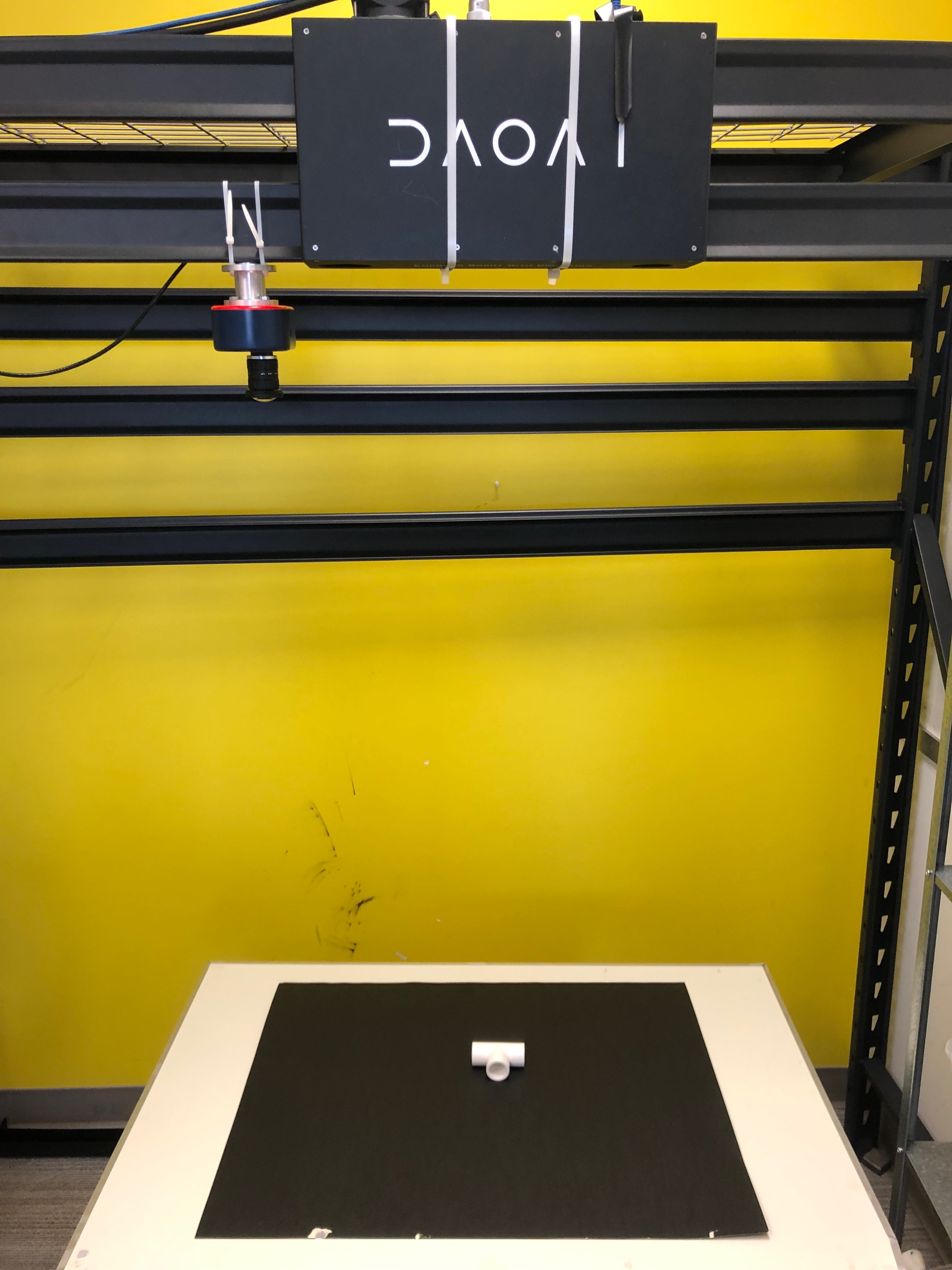
Place your object under the camera and try to put it as close as possible to the center of your working environment (center height of the working cell, and at the center of the image) to capture the sample image while making sure that the object is lying fully in the field of view of the camera. It’s useful to run the camera node continuously, and turn on the point cloud view to see the image quality of the object.
Isolating the object
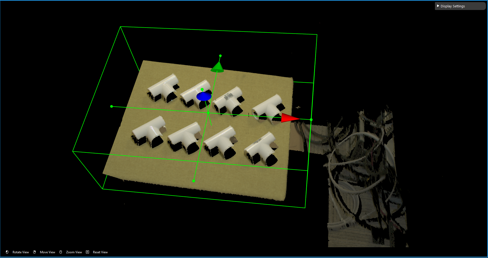
Usually the camera field of view will be larger than the region of interest, thus the first step usually is to setup the boundary for the useful information. You could run to the Section 2 Cloud Process node, and make sure the Adjust Bounding Box options was on in the cloud process display setting. Then execute the Cloud Process node. Then you could adjust the bounding box.
Tip
When adjust the bounding box, you could press R to reset to the original view. For more information of Adjusting Box, checkout this article.
Define the Model with the Image
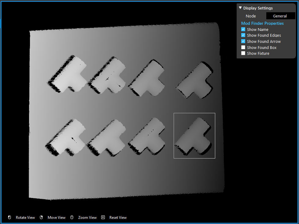
We use the depth output from the DA CloudNDepth Conv node, and now we run the Mod Finder node once to load in the image.
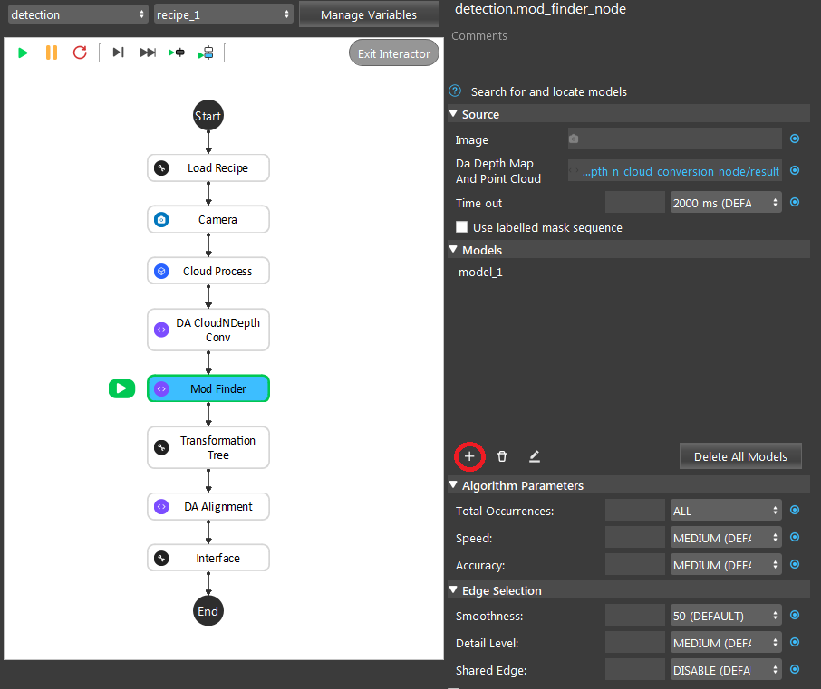
Then click add model, then select a bounding box on the image.
To define a model, click the + sign.
Then defining the model in scene.
Poses Generation & Transformation
The DA Alignment nodes in Detection flowchart will generate the poses output the Object in Cloud relation for further calculations. We will skip this part here, and you can checkout the articles for DA Alignment node. Which it will cover the pose transformation detail as well.
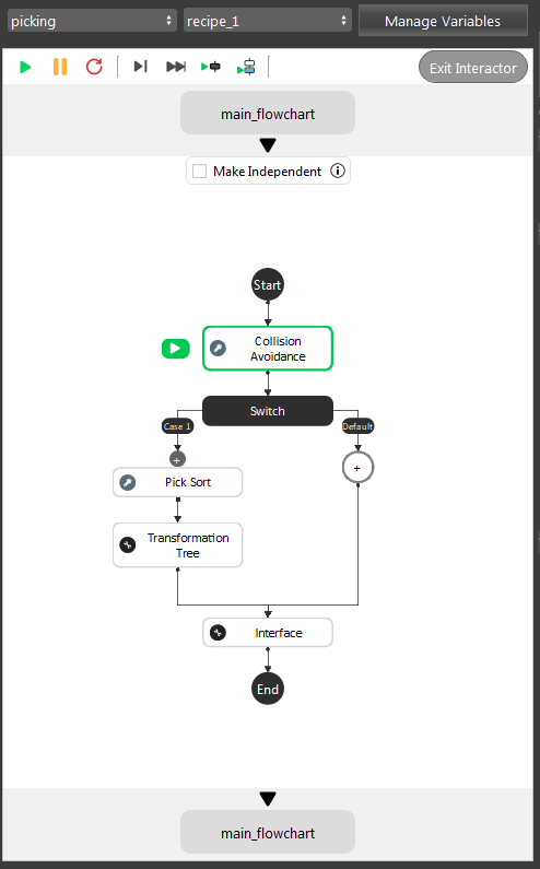
After the Detection pipeline, you have the objects locations in scene. Then, these poses will need transformations, since the robot requires the Tool in Base relation for all the objects. As the image shown above, our template will process the collision avoidance for these objects in scene. Then providing the orders for these objects, and send it to robot.
You can checkout details about `Gripper node <>`_, `Collision Avoidance node <>`_ and `Pick Sort node <>`_.
After these transformations, robot will receive a pose regarding to its Tool in Base relation to perform picking.