You're reading the documentation for a development version. For the latest released version, please have a look at master.
DaoAI Camera
Content
Physical Camera Wire Connection
On the front side, the camera has one light projector (1) and one camera lens (2) shown in the picture down below.

On the backside, the camera has one 3.0 USB port (1), one power source (2), and a fan (3).

Connect the camera via DaoAI Camera Studio (physical camera)
For more detailed steps to use the DaoAI Camera Studio Manual . First clicking on the DaoAI Camera Studio icon to open the software, pressing the refresh button, searching, and updating the available cameras. If there is an available camera in the list, by clicking on the list box on the left side, the serial number of that camera will pop up in the box. Then, you can click “Connect” button to connect the camera with the studio software.

To disconnect the camera, you can either close the software or press the camera serial number printed on the top right corner. The “Manage Cameras” window will display, then you can press the “Disconnect”.

Basic configuration for capturing
You can click on the “+” button to add multiple frames when capturing the image. To delete the frame, you can click on the trash bin button on the right. However, the minimum number of the frame that you can have is 1.

In the frame, you can adjust the 3 parameters, exposure, brightness, and gain respectively. Adding multiple frames will help the camera to capture more details and features in the image; however, the capturing time will get longer as well. By clicking on the “Capture” button to capture an image. The “Auto” button will allow the system automatically adjust the setting to capture the best shot image. The “Live” button will trigger the camera to constantly capture the images. To stop it, you just need to click on the “Live” button one more time.


You can also use the manual bar highlighted in the image down below to check out the image quality in different modes.

ROI (Optional)
If part of the image point cloud is unclear, the software allows you to switch the mode from “Point Cloud” to the “2D color” to readjust the area that has bad point cloud quality.

Once clicking the “Use ROI” button, you can select the specific area of an image to edit.

Then you can click the save button to confirm the area and perform the adjusting. Once finish adjusting the area, you can click the “…” on the top right to delete ROI.


Gap Fill (Optional)
Another general function that has been used quite often is the “Gap Fill” function. The function can help you to repair and optimize the point cloud image by automatically filling the point cloud captured from the Studio.


Saving the studio file
When finishing editing the settings, to save the caputring configuration and loaded into the Vision Studio for using it for real detection project, you can click the “File” button and select the “Save Setting As” to save the setting as cfg. Remember the name of the “.cfg” file, as you will need to load it in the Vision Studio.


Connect the camera via DaoAI Vision Studio
Open the Vision Software and click on the New Project button on the top left.

In the New Project dialog, you should name the project and select the file location, then press “ok”.

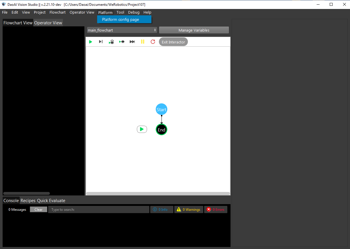
Once finishing creating the new project, you should click the Platform to config the camera, robot, and server settings.
All three categories are listed on the left side of the dialog and highlighted by the blue bar. You can add cameras, robots, or servers by pressing the “+” button.

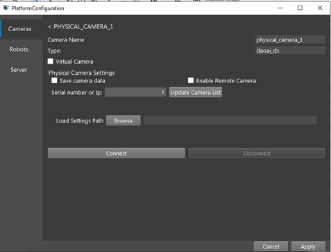
Under the Type, click the camera box to view the whole list of options and select the camera that is going to be used for the application by clicking the Accept button. Then, a new dialog will pop up for configuring the specific camera. You can load the cfg file saved from the studio into the “Load Settings Path” as the setting used for configuring the camera node in the Vision software. To delete the camera, you can select the camera and press the trash bin icon to delete it.

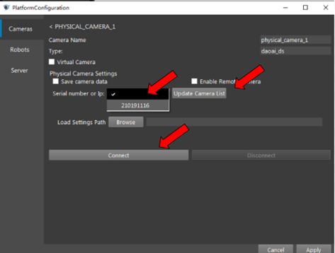
To add the real camera, you should press the “Updated Camera List”, then press the blank box on the left to discover if the camera’s serial number has been updated. If the number pops up, you can select the number by pressing it. The load Setting Path function allows you to load the cfg file, which contains the setting you configured in the studio to enhance the quality of the image shot from the camera. Then, press the “Connect” button to connect the camera with other nodes.
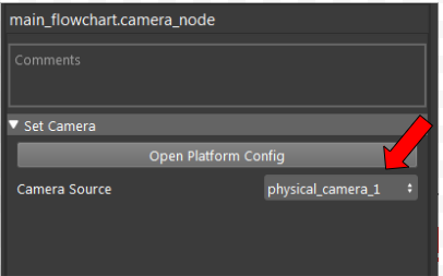
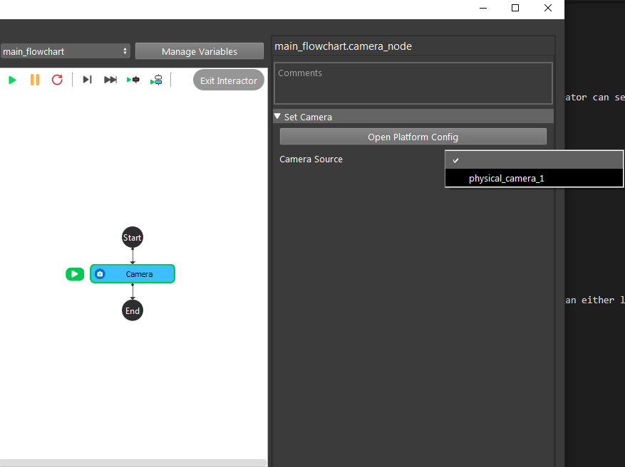
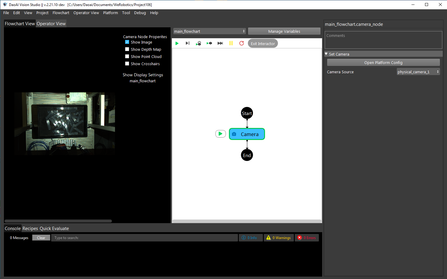
Once the camera has been connected with other nodes, you should select the correct physical camera number in the Camera Source box.
Connect the virtual camera via DaoAI Vision Studio
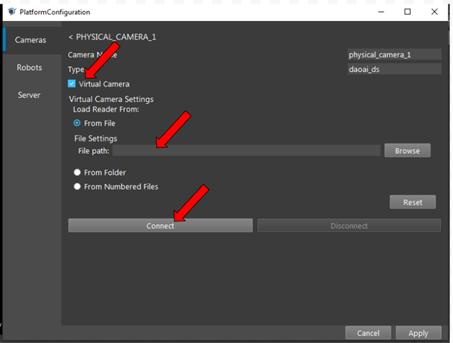
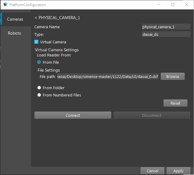
You can load dcf/daf files that were generated in the past as the camera output. To do so, you should check the Virtual Camera box, and choose the option to load the dcf files. You can either load the entire dcf folders or just load a single dcf file. Then press the “Connect” button to connect the camera node with the other node.
Use Camera with Camera Node
Once configuring the camera, switch back to the flowchar template and right click the “+” to add the camera node.
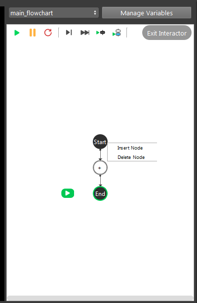
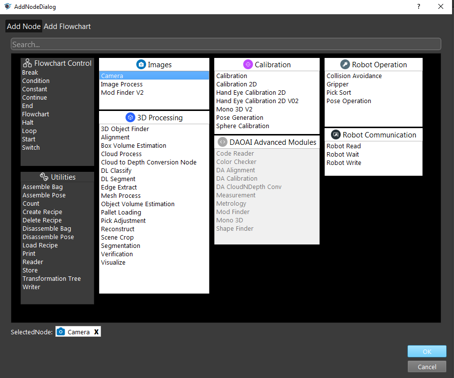
Then click on the camera node and select the correct physical camera configured inside the camera source.
Common Issues
USB 3.0 cable issue
The DS camera USB has to be plugged into the USB port 3.0 in order to be functional.
cfg file doesn’t match
The cfg generated by the old version camera studio cannot be used in the later version. Be sure the version camera studio is under the same version as in the third party’s SLC.
Not able to find the camera
This issue normally caused by the version conflict. Making sure the camera studio is in the latest version.
In addition to allowing the connection of Physical Daoai Camera, DaoAI Vision Studio offers the Virtual Camera function in order to allow you to load existing image files.
On the top menu bar, select Platform -> Platform config page.
Select Cameras on left side menu bar and click +, then choose DaoAI Camera, Then click Accept button below.
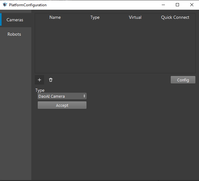
Now you have two options to proceed: Virtual Camera or Physical Camera (Default).
Physical Camera
Click update Camera list and select the Serial Number of the camera, then click Connect.
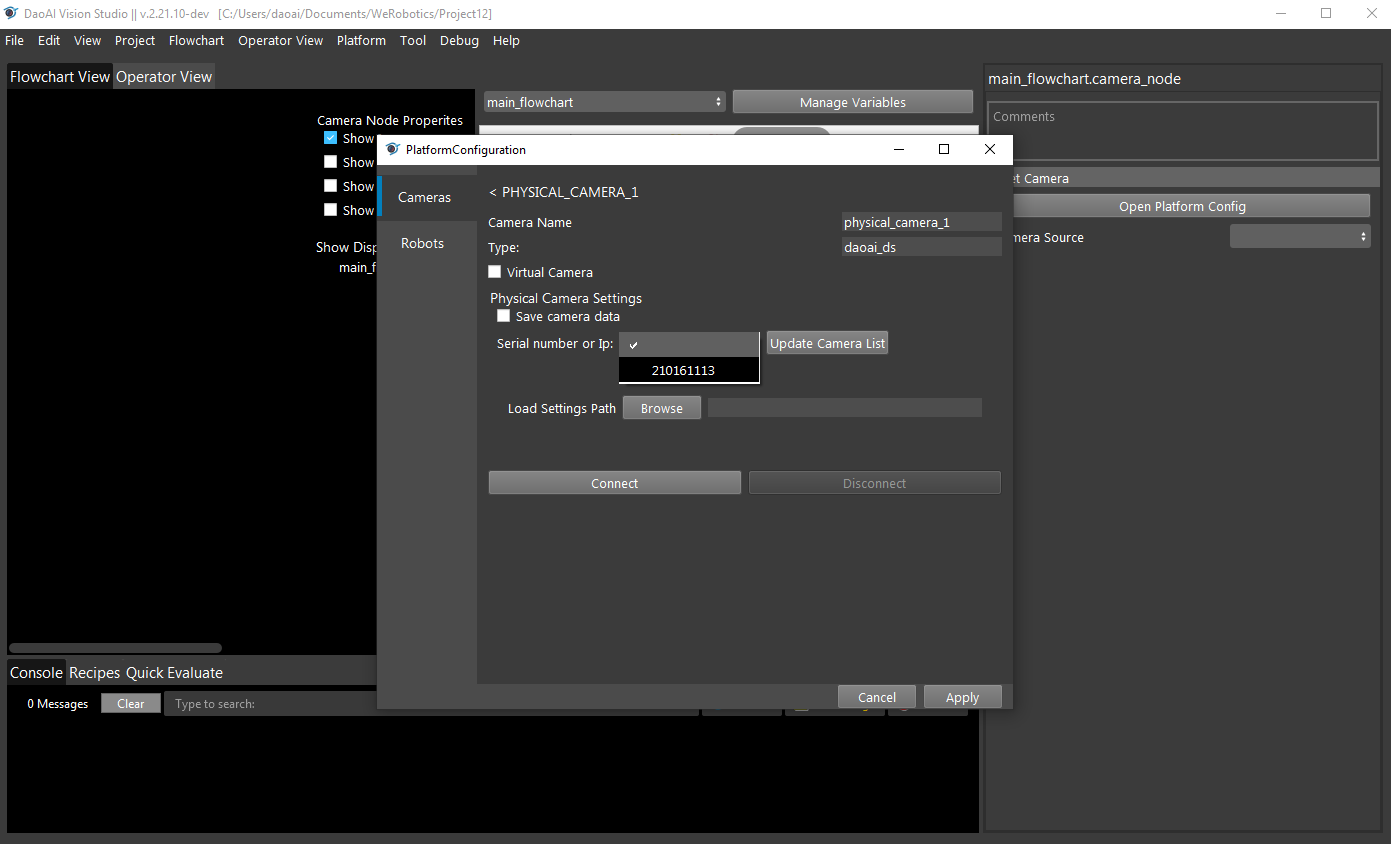
You can also load a camera setting file when connecting to a camera. The settings include projector/camera parameters when capturing 2d images and parameters used when generating the point cloud. The camera config file (.cfg file) is created by DaoAI Camera Studio Program. Refer to Camera Studio User Manual for details on how to adjust camera parameters and exporting config as a file.
Virtual Camera
Select Virtual Camera, Click Browse to Choose the image files you want to load, then click Connect.
Note
Select the camera name you just created in the Camera Source and run the camera node in the flowchart.
Save Image Data
You can save your image data into your local directory for future use.
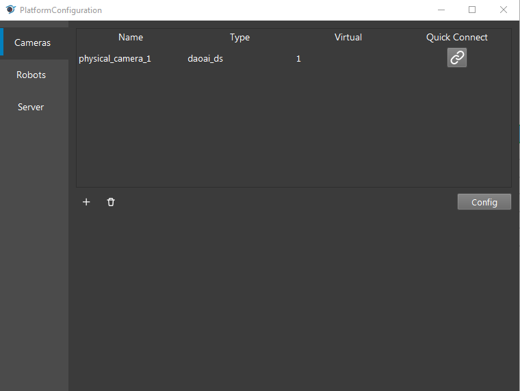
Open Platform Configuration, and click into Cameras. Click into the connected camera.
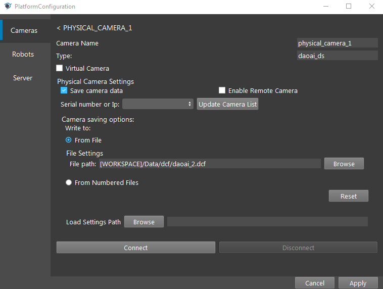
Click Save camera data, and select either From File**(by default) or **From Numbered Files. From File will save the captured image into a designated directory and file.
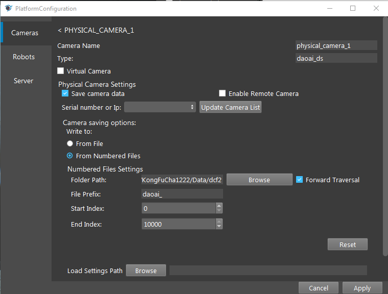
From Numbered Files will save the data into the designated directory. And as you capture more and more images, they will all be saved into this directory with prefix and index number.
These saved data will contain the point cloud, 3D data etc into a .dcf file. These .dcf files can be loaded using virtual camera.