You're reading the documentation for a development version. For the latest released version, please have a look at master.
Daoai Gige Camera
Physical Camera Wire Connection
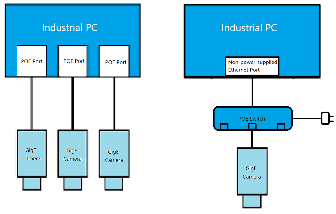
Gige Cameras are usually connected through Ethernet cables, you can find the ethernet port on camera.

The Gige camera can directly connect to the Power Of Ethernet(POE) port of the industrial PC, or through a POE switch to connect to a none-power-supplied ethernet port.
Attention
In order to have stable connection, the ethernet cable need to meet industrial usage standard, and CAT6 above. If there is any sudden disconnection, most likely it’s the cable issue.
Once camera connected, the power and POE connection status indicator on the camera and industrial pc should be green. Otherwise, could check if the industrial PC/switch POE power is stable or not.
Connect the camera via DaoAI Vision Studio
Once physically connected, on the top menu bar click the Platform -> Platform config, click the + button, and select DaoAI Gige Camera, click accept.
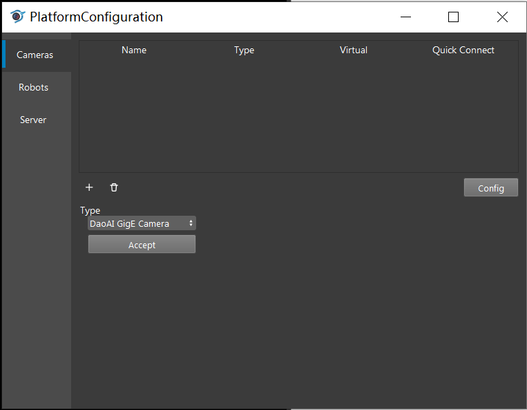
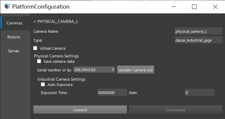
Click the Update Camera List, and select the camera you wanna connect. In order to tune the camera, sometime you want to change the Exposure time and Gain. Then click connect button.
Attention
In order to connect the PC with the Gige camera, both has to fall within the same sub network. Check the Network configuration
The larger the exposure time and gain, the brighter the image. Some model of the camera has a available range for the exposure time and gain, will need to check the model.
Connect the virtual camera via DaoAI Vision Studio
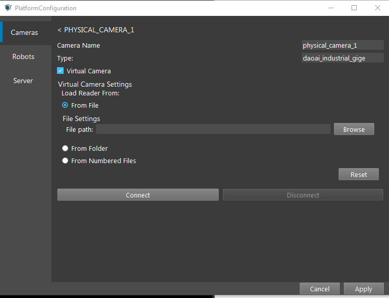
The virtual camera will read the *.png files, and select the way you would like the system to find the *.png files.
Attention
From file: Select a single png file
From folder: It reads out all the *.png file from the folder
From numeric: Read specific files with dedicated prefix.
Use Camera with Camera Node
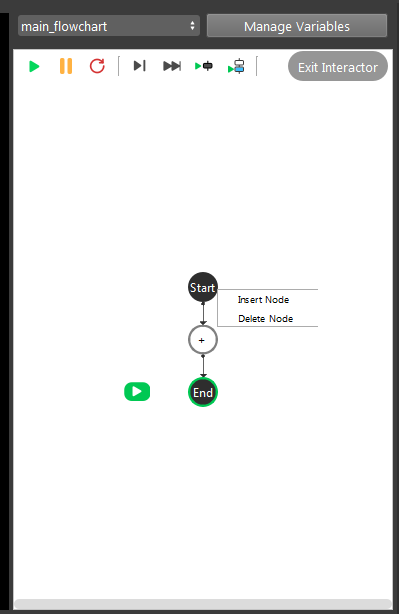
Once configuring the camera, switch back to the flowchart. Right click the “+” sign and add the camera node.
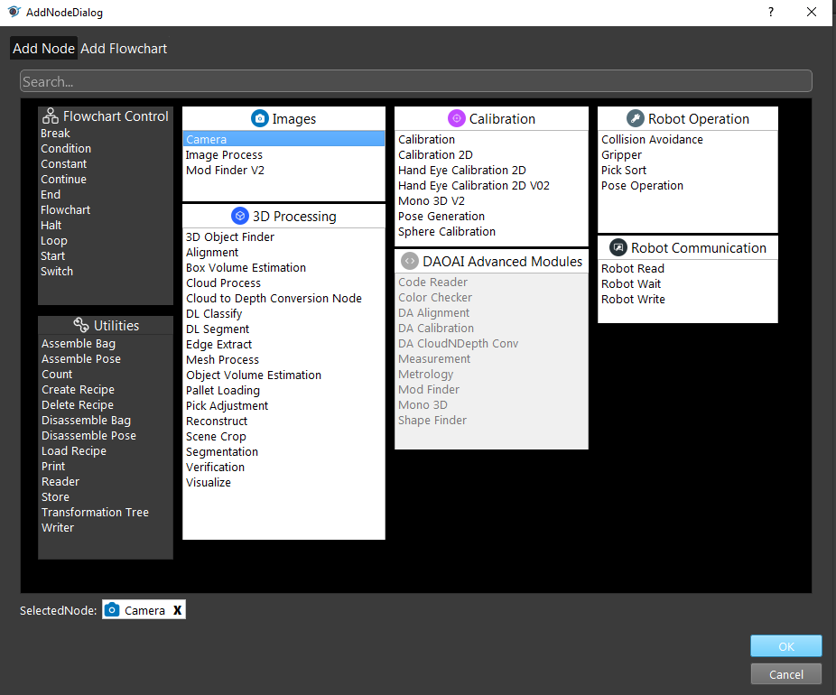
Then click on the camera node and select the camera you just added in platform config window.
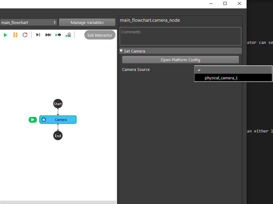
Now if you run the Camera node, it will generate camera capture or virtual camera image.
Network configuration
In order to let the camera and industrial pc to connect, they both need to fall in the same subnet. Usually the camera was configured to automatically get an IP from the industrial PC, in this way, the camera can get an IP which can directly communicate.
Sometimes, the Gige camera was configured to a different subnet that the POE network driver. In this way, you need to either change the PC network to a static IP that could match the Gige camera, or set the camera to automatically get a new IP address (usually by reset to factory settings). The subnet usually means the last number of the ip is different, but all the other numbers are the same, and the mask is 255.255.255.1
To change the PC network to static IP, first you need to know the IP address of your camera. Open command line prompt, enter
ipconfig. You can see your computer IP and the connected camera IP here. Leave the window open and proceed to next step.Next thing is to press
Win+Rand enterncpa.cplto open Network Connection window. Find the Network adapter for your computer network connection, and right click > Properties.
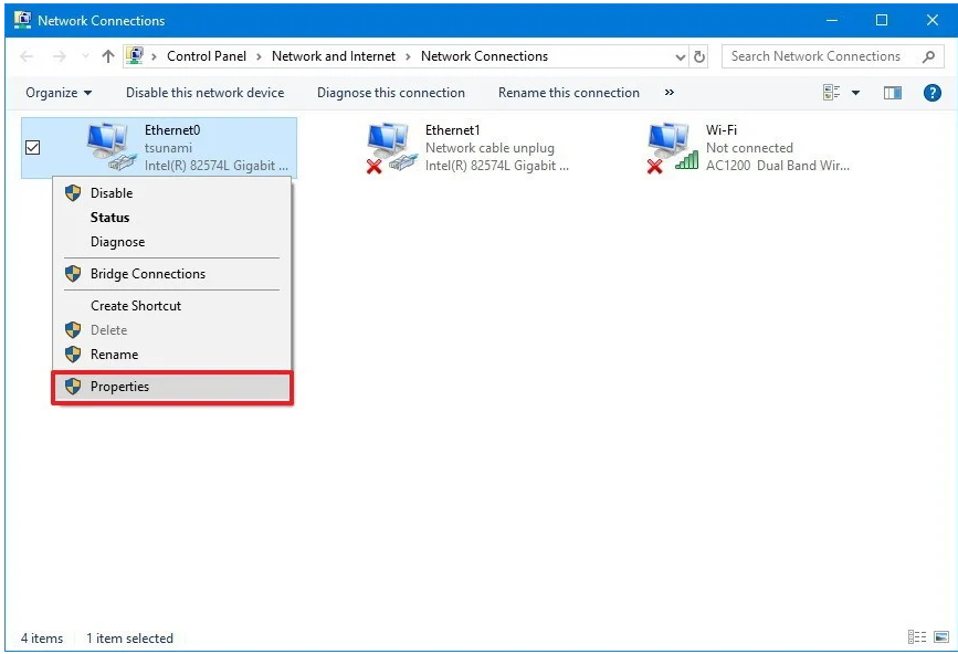
Find the
Internet Protocol Version 4(TCP/IPv4) Properties, double click it and you should see the following window.
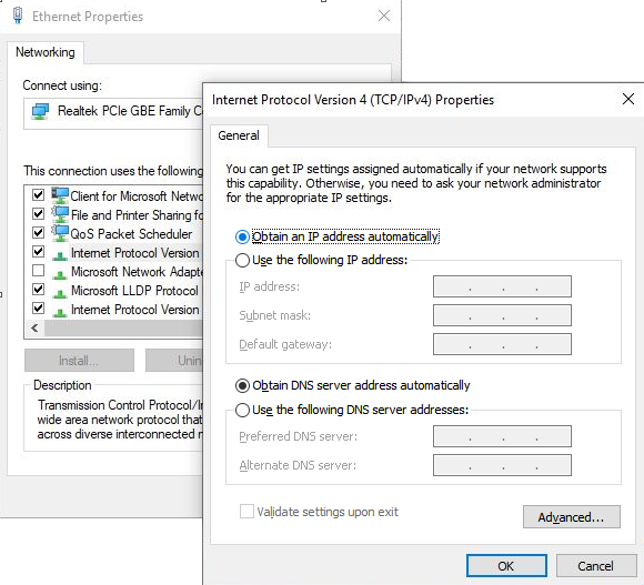
Change the
Obtain an IP address automaticallytoUse the following IP address. Then change the first lineIP addressto match first three parts of the camera IPv4 address. For example, if your Camera IP address is 196.254.42.xxx, then you should enter 196.254.42.yyy(yyy must differ from xxx).Then in the next line, enter 255.255.255.0 for subnet mask. Click OK to save the changes.
Common Issues
Packet Loss
First confirm the Gige Camera IP is under the same subnet with your PC.
Then press
Win+Rand enterncpa.cplto open Network Connection window. Right click the Ethernet port your camera connects to. Click Properties- Find
Client for Microsoft Networksand clickConfigurebutton. 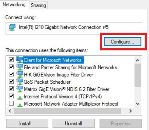
- Find
- Go to Advanced and in the Property List find
Jumbo Packet. In the Value dropdown list, select 9014 Bytes. 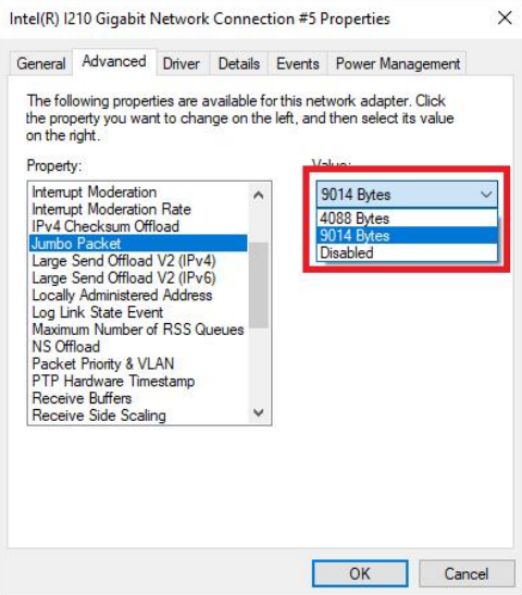
- Go to Advanced and in the Property List find
- Continue in the Property List, find
Receive Buffers, set the value to 2048. 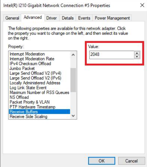
- Continue in the Property List, find
- Continue in the Property List, find
Transmit Buffers, set the value to 2048. 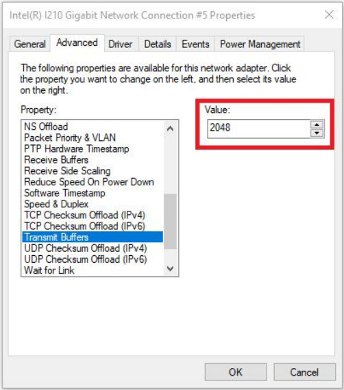
- Continue in the Property List, find
- Continue in the Property List, find
Speed & Duplex, set the value to 1.0 Gbps Full Duplex. 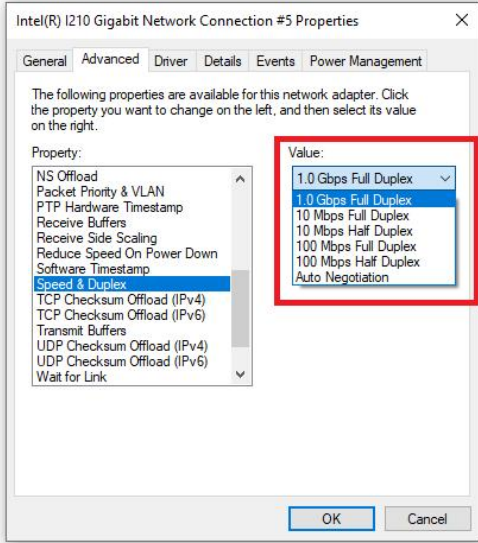
- Continue in the Property List, find
Click OK to save your changes.