You're reading the documentation for a development version. For the latest released version, please have a look at master.
Metrology Node
Overview

Inputs and Outputs
Input |
Type |
Description |
|---|---|---|
Image |
png |
The image to be measured (Camera, Reader etc.). |
Timeout |
Double |
The maximum measurement and validation time for calculating in milliseconds. |
Use Reference Frame |
String |
The name of the mod finder node to use the reference frame from. |
Show Interactive Display |
Bool |
Whether Interactive Display is being used. |
Output |
Type |
Description |
|---|---|---|
allTolerancesPassed |
bool |
Whether all tolerances are passed. |
numFailedTolerances |
int |
The number of tolerances that are failed. |
numWarningTolerances |
int |
The number of tolerances that are in warning. |
toleranceResult |
SMetrologyResult |
The metrology results. |
Node Settings
Data Source

- Image:
The image to be measured (From Camera, Reader etc.).
Metrology Settings

- Timeout (Default: Disable):
The maximum measurement and validation time for calculating in milliseconds.
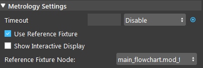
- Use Reference Fixture (Default: False):
Check this box to use reference fixture (e.g. from Mod Finder). Please refer to Reference Fixture System for more information.
- Show Interactive Display (Default: False):
Check this box to edit features on images.
Features

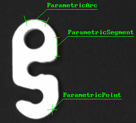
- Parametric Feature:
Define fixture in absolute position by drawing in the image.
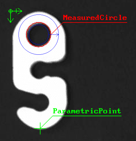
Parametric features are displayed in green colour.
Available parametric features: Local Frame, Arc, Line, Segment, Edgel, Point, Circle.
- Measured Feature:
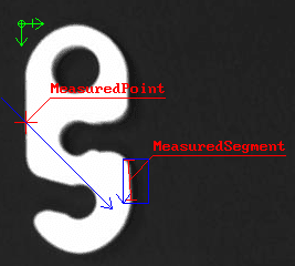
Define a feature by finding it from the search region (relatively fixed with global frame), which is defined by the user.
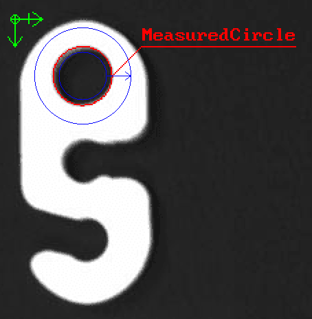
Region setting: decides the blue search region of the feature (one of Ring/Ring Sector/Rectangle/Segment/Arc).
The arrow indicates the detection direction of the search region.
For Ring and Ring Sector region, the arrow’s direction indicates the Start Radius and End Radius. (Tail: Start Radius; Head: End Radius)
Red = detected geometry; Blue = search region.
Available measured features: Segment, Edgel, Arc, Circle, Point.
Measured Feature Parameters
- Threshold:
A high threshold only keeps edge with strong contrast. A low threshold will include fainter edges.
- Smoothness:
Strength of the noise reduction filter when detecting edges.
Range [0.0 ~ 100.0]
- Data Angle Tolerance:
Whether edges along a transition are considered is based on the angle (direction) of the transition compared to the scan direction of the search region.
This angle tolerance determines the range of accepted angle (direction).
- Edge Selection Rank:
Setting rank “1” will fit the segment to the edges closest to the beginning of the search box.
Setting “Disable” will fit to all the edges found in the search-box.
- Constructed Feature:
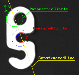
Define fixture from other base features, such as define a mid_point from a segment, or define a circle base on 2 points.
The base features used can be a combination of Parametric, Measured, and Constructed features.
Available constructed features: Local Frame, Arc, Line, Segment, Edgel, Point, Circle.
Tolerances
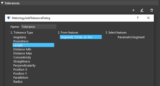
Tolerances’ labels will be displayed when “Show Interactive Display” is not checked.
- Green: Passed
pass_min > value > pass_max
- Yellow: Warning
warning_min > value > warning_max
- Red: Failed
value < warning_min OR value > warning_max
- Tolerance Type
Pick a Tolearnce Type from the list.
- From Features
Select a method to calculate the tolerance value.
- Select Features
Select the Features to be used to calculate the tolerance. (Follow Step 2’s Feature Type)
- Example:
Angularity
One Linear, One Edgel
Select 1 ParametricLine & 1 Parametric Edgel
Procedure to Use
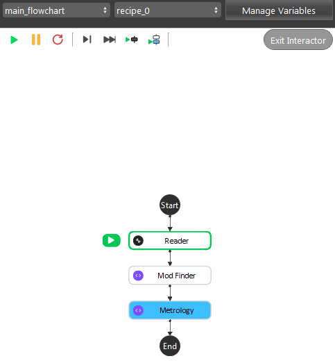
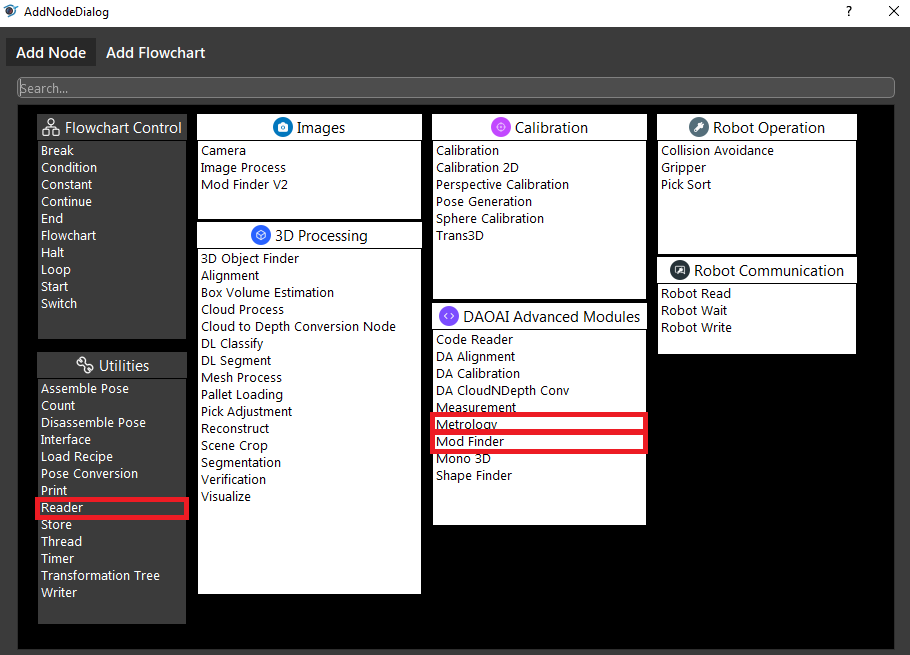
- We will need a few more nodes to demonstrate the Metrology node. Insert Reader, (2D) Mod Finder, Metrology.
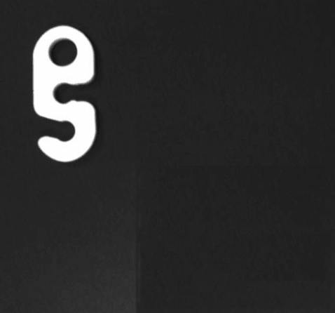
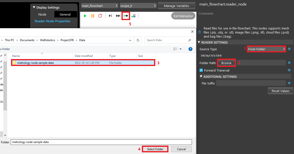
- In Reader node, select the metrology node sample data folder. You can get the data here.
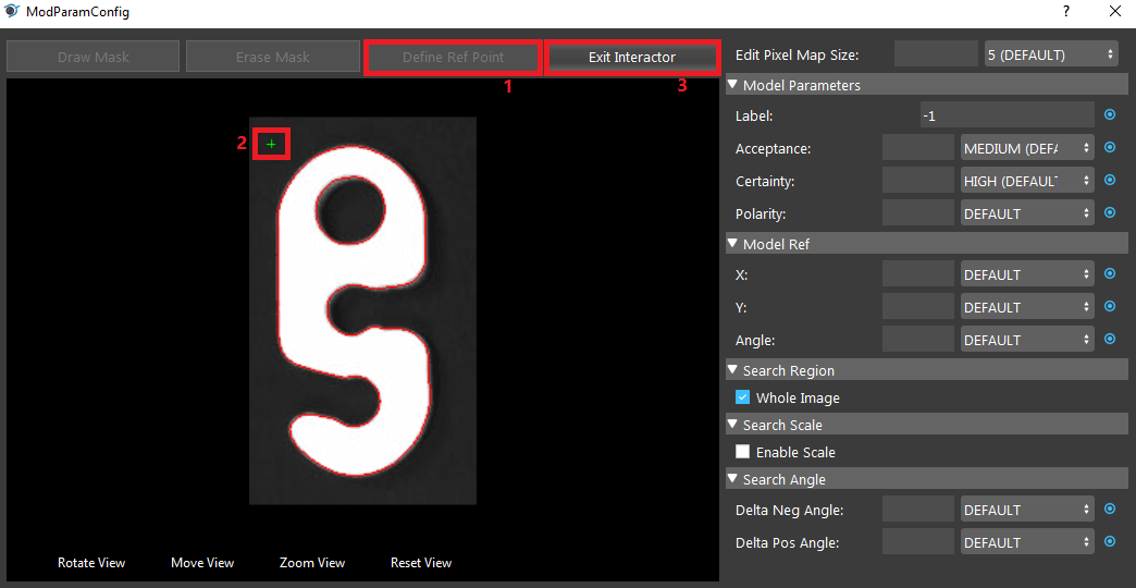
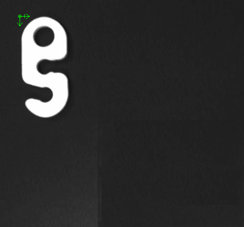
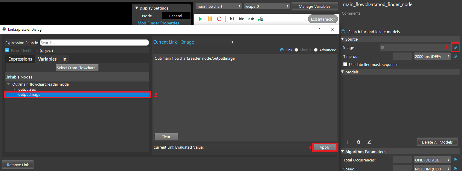
- In Mod Finder, link the Reader’s image output, define a model, and click “Define Ref Point” to define a reference point.
- In Metrology, link Reader’s image output. Then check “Use Reference Fixture” and “Show Interactive Display”. Select the Mod Finder node as the Reference Fixture Node.
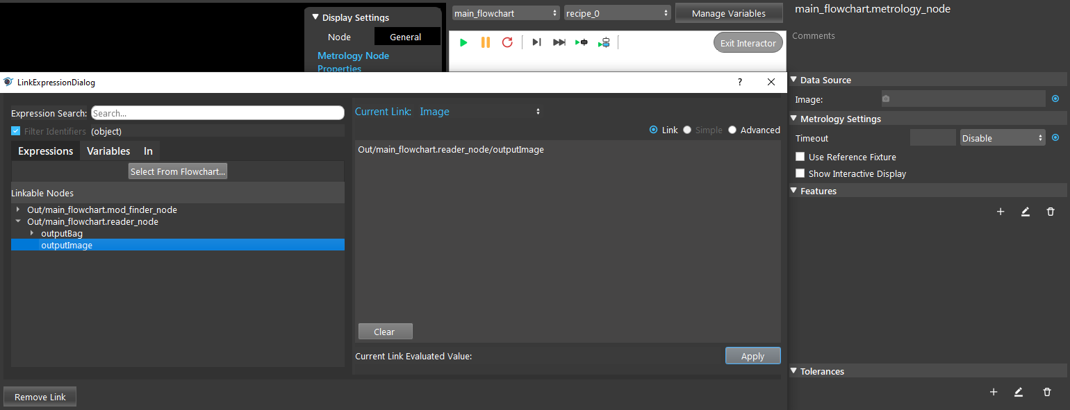
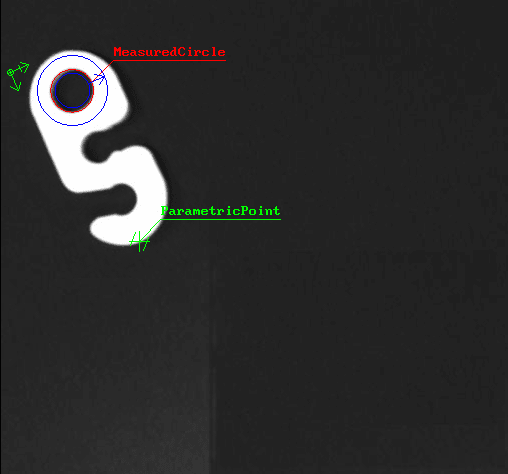
- Add a measured circle feature. The red circle with label is the circle found in the blue search region.

- Add a parametric point feature. Drag it on the image to change its location.

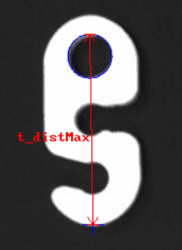
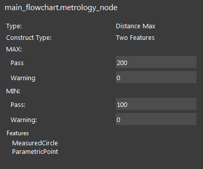
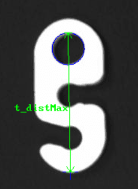
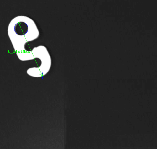
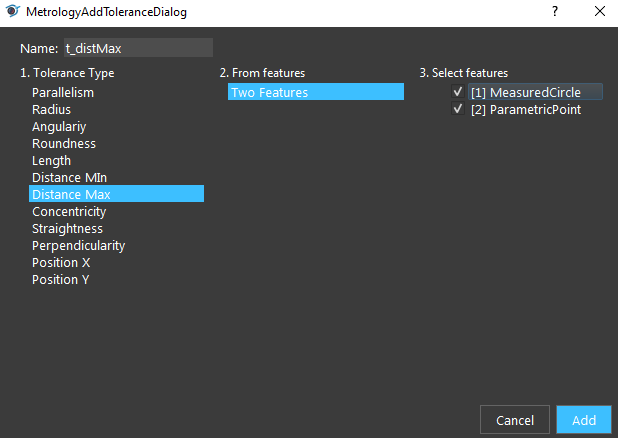
- Add a Distance Max tolerance. Change its name to “t_distMax” with the following settings. Uncheck the “Show Interactive Display”. The tolerance is shown in red (failed) in the image.
- Check the t_distMax’s value from Quick Evaluate. Enter “t_distMax” as the tolerance_name and click “Re-Evaluate”.

- Change t_distMax’s Min pass to 100, and Max pass value to 200. Since tolerance value is between 100 and 200, it is now passed (green).

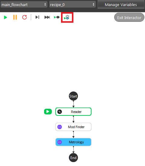
- Click “Run to Selected Step”. You should see that the features are moved relatively to the reference fixture and a new tolerance is calculated.
Exercise
In steps, explain how to use the Metrology node that check if a hook’s circle’s Y position is less than 200.
Answers for Exercise
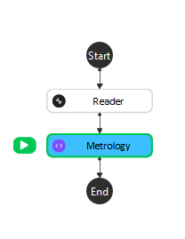
- Insert a Reader node and Metrology node. Link a hook image in Reader, and in Metrology link the image input to Reader’s image output. (Refer to Procedure to Use section for detailed steps)
- Add a parametric local frame at the position (0,0).
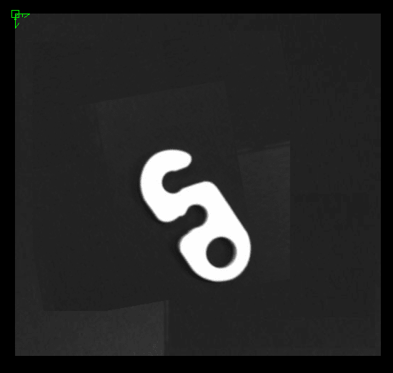
- Add a measured circle.
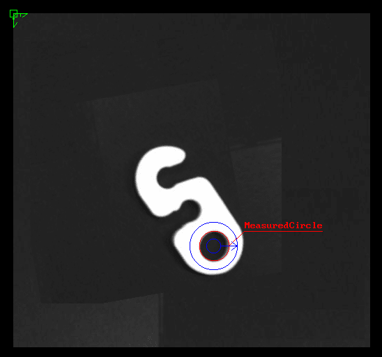
- Add a tolerance (“t1”) with the Position Y Tolerance Type.
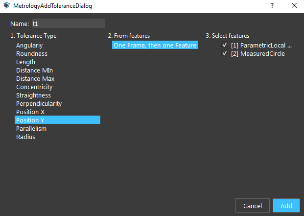
- Change t1’s max pass to 200.
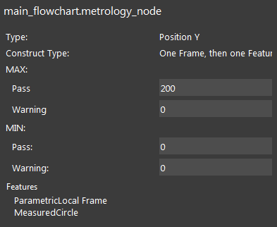
- Disable “Show Interactive Display” and run the node. The tolerance is failed.

- Evaluate the tolerance value from Quick Evaluate. 334.48 > 200, hence it fails the tolerance.

