You're reading the documentation for a development version. For the latest released version, please have a look at master.
Shape Finder Node
Overview
Shape finder node is used to find shapes on gray scale images using edge based searching.
Input and Output
Input |
Type |
Description |
|---|---|---|
Image |
Image |
The source that is used to search for shape. |
Time out |
Int |
Time in miliseconds that the shape finder will search before terminatation |
Output |
Type |
Description |
|---|---|---|
labelledPose2dSequence |
Vec<Pose2D> |
Vector of pose 2d preserving order from labelled mask sequence. |
shapeMasks |
Map<Image> |
A map of model masks. (Mask is created using the shapes edges) |
shapeLocation |
Map<Vec<Pose2D>> |
A map of vector of 2d shape locations (Pose2D of shape center). |
numFound |
Int |
The total number of Shapes found. |
success |
Bool |
Boolean value indicating the search is successful. |
Node Settings
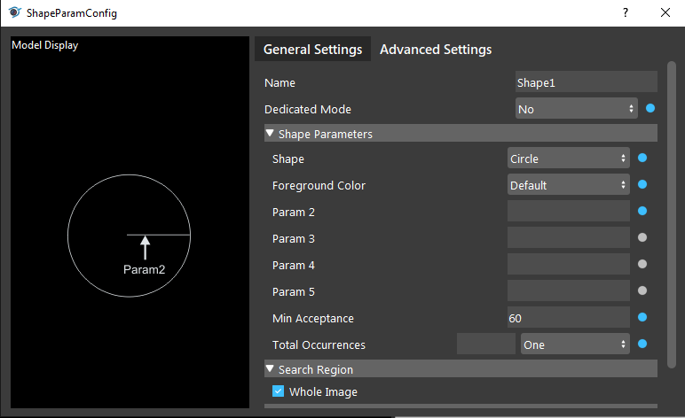
The following image demonstrates the shape finder node settings
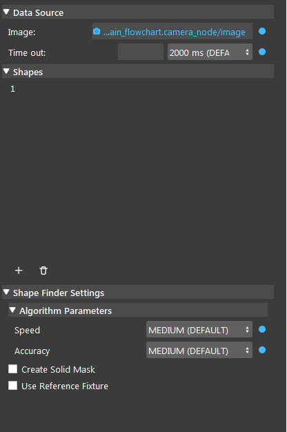
Source Parameters
Image:
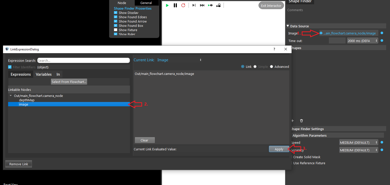
The source that is used to search for shape. Using link expression to link the image.
Time Out (Default value: 2000 ms):
The time limit for the node to run. When the running time of the node reaches the time limit. The node will terminate and return the current output.
Shape finder settings
Create Solid Mask:
By defualt the output mask only includes the detected shape edges. When checked, the output mas will be filled to create a solid mask.
Use Reference Fixture:
This node can be used for generating fixture. Please refer to Reference Fixture System.
Algorithm Parameters
Speed (Default value: MEDIUM):
The speed of searching. Larger value means faster speed but less accuracy.
Accuracy (Default value: MEDIUM):
The accuracy of searching. Larger value means heigher accuracy but slower speed.
Shapes
General Settings
Name:
Name for the shape created, you can give whatever name you like.
Dedicated Mode (Default value: No):
Use a dedicated algorithm and the search_region, scale, and speed settings will be ignored if choosing yes.
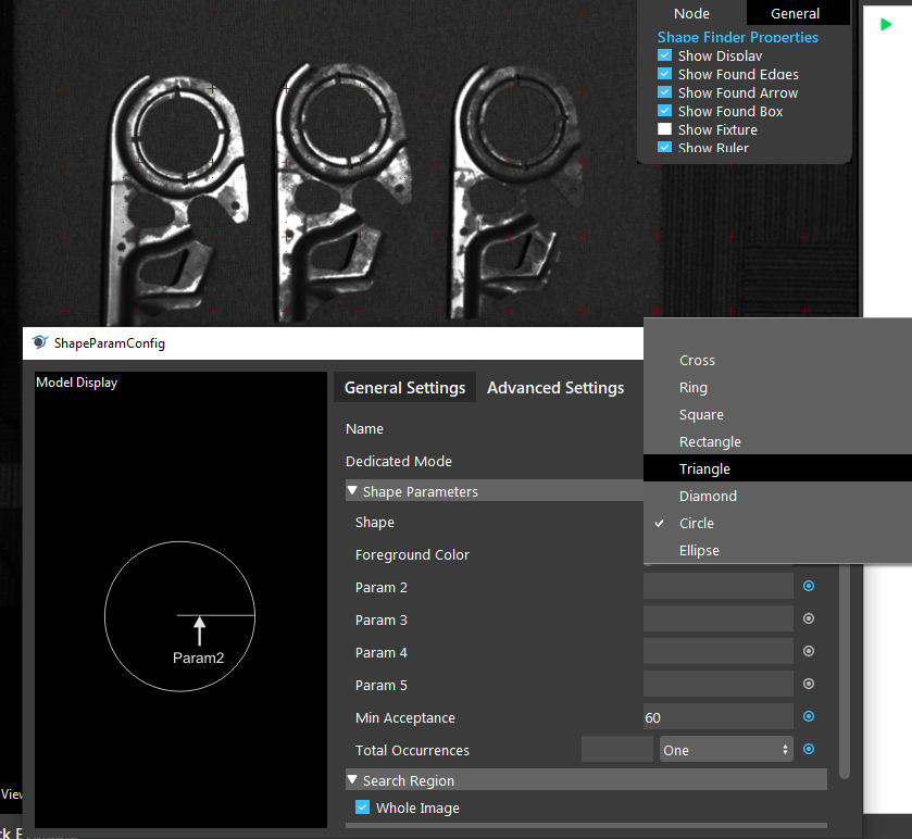
Shape (Default value: Circle):
List of shapes available for shape finder.
Foreground Color:
The color of area within the shape to be accepted as a occurrence.
Param[2-5]:
Parameters on shape dimensions, the unit used here is in pixels | number of parameter needed varies on different shapes.
Min Acceptance (Default value: 60):
The minimum matching score where an occurrence is accpeted. An occurrence will be returned only if the match score between the target and the model is greater than or equal to this level.
Total Occurrences (Default value: One):
Maximum number of Shapes to search before terminatation. When the number of found matching shapes is equal to the set Total Occurrences value, the node will terminate and return the current result.
Whole Image (Default: Checked):
When checked, the node finder will search on the whole image. When unchecked, the node finder will search on the restricted area of the image that you need to define.
Enable Search Scale (step: 0.1):
When checked, the node finder will also search on scaled image of the input image from scale Min to Max with a step of 0.1. When unchecked, the node finder will only search on the input (non-scaled) image.
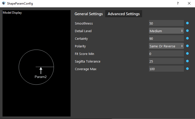
Advanced Settings
Smoothness (Range[0-100], default: 50):
Sets the degree of smoothness (noise reduction) applied to the model images and target images during the edge extraction. | A setting of 0 indicates almost no noise reduction effect, while a setting of 100 indicates a very strong noise reduction effect.
Detail Level (Default value: Medium):
Sets the level of details to extract from model images and target images during edge extraction. | The detail level determines what is considered an edge/background. | A heigher detail level will include more edges than a lower detail level.
Certainty (Range[0-100], default: 90):
Sets the certainty level for the score, as a percentage. | If both the score and target scores are greater than or equal to their respective certainty levels, the occurrence is considered a match, without searching the rest of the target for better matches. | Higher certainty results in better accuracy but lower running speed. A good certainty level should be slightly lower than the expected score, so that the search terminates as soon as a match is found.
Polarity (Default value: Same Or Reverse):
Sets the expected polarity of occurrences, compared to that of the model. | “Same” means the foreground should be same as you specified. | “Reverse” means the foreground color is reversed. | “Same Or Reverse” means all that is “Same” or “Reverse”. | “Any” means you do not care about the foreground color.
Fit Score Min (Range[0-100], default: 0):
Only supported in dedicated mode. | Sets the minimum expected occurrence fit score.
Sagitta Tolerance (Range[0-100], default: 25):
Only supported in dedicated mode for Circle or Ellipse. | Sets the tolerance for finder deformed circles (allowable radii variation) for a model. | A value of 0 means that the circular shape being sought needs to be as close as possible to a perfect circle. | A value of 100 means that the algorithm as the maximum tolerance for finding deformed circles.
Coverage Max (Range[0-100], default: 100):
Only supported in dedicated mode for Circle or Ellipse. | Specifies the maximum expected model coverage.
Procedure to use
Open a workspace in DaoAI Vision Studio.
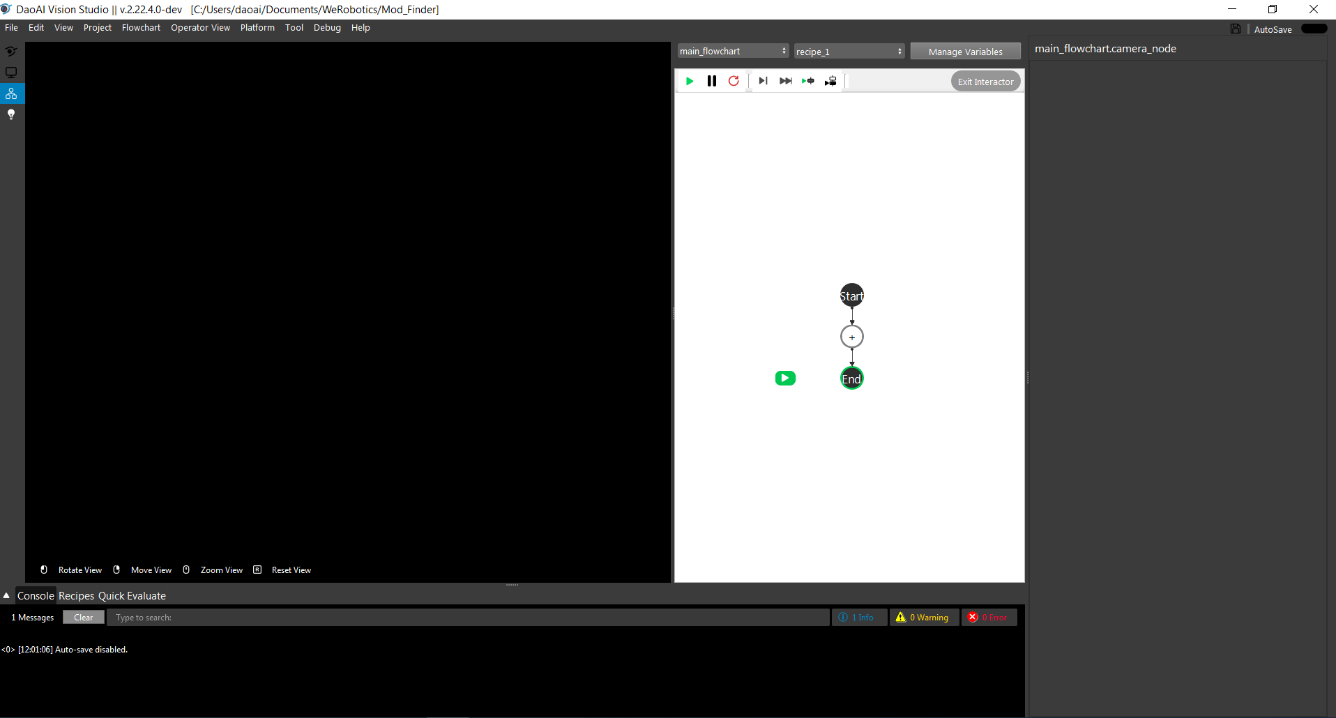
Insert a Camera node to get the source image.
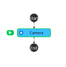
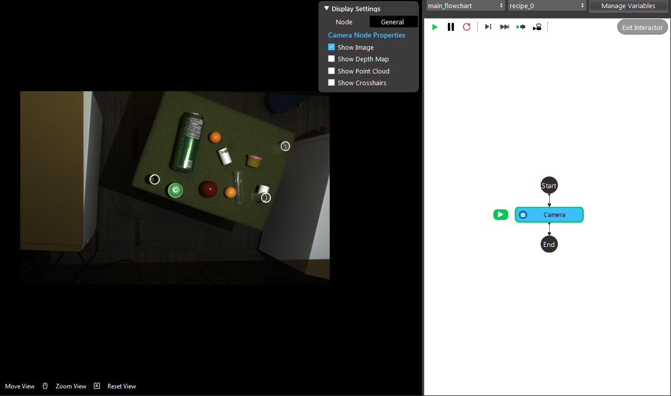
A virtual image is used to demonstrate. Refer to System Overview, Tutorials on how to connect to camera.
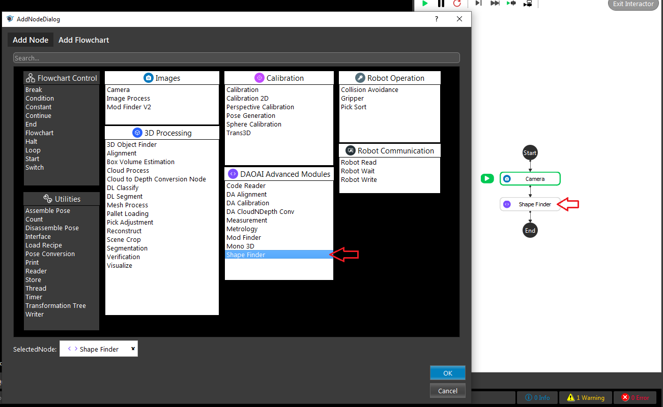
Add a Shape Finder node after the camera node
Link the input Image to Camera node output
Click the ‘+’ sign to add a shape, give it a name you prefer and click confirm
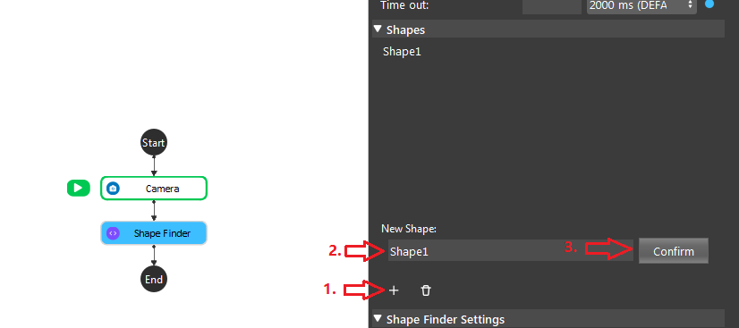
Double click the shape you just created, select a shape, and fill in the params, you can also adjust other settings, close the window when you are done.

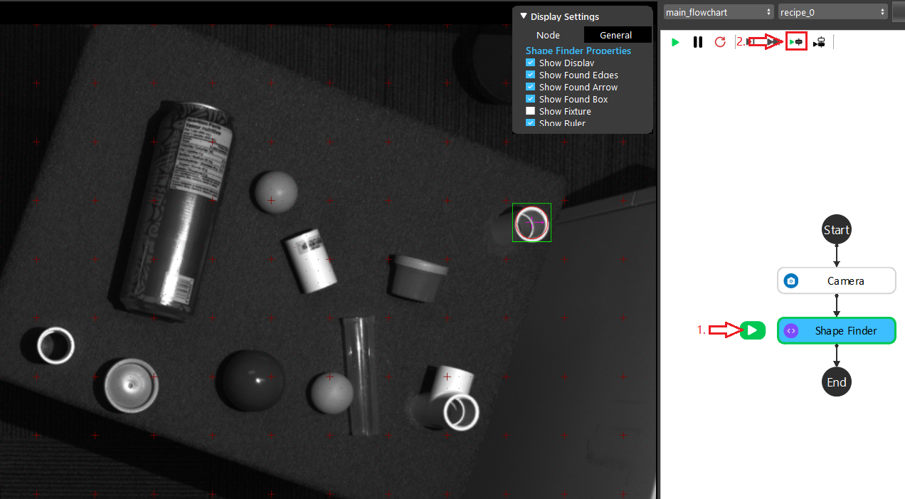
Select the Shape Finder node if its not selected already, and click run select step, then you should see the result on the left view port.
General process of Using Mod Finder Node
Link input image.
Run node once so the input image shows on the display.
Define shape, click on “+” button to add a shape, and select a shape to be searched in the image and input its parameters.
(Optional) adjust other shape settings or Advanced settings in the shape config page.
Run the node with other images. The found occurrences of the shape will be displayed in the target image.
Use the position vector for further processing to get the picking pose of the objects in the scene.
Excercise
Here is the link to a .dcf file which is used as input.
Try to come up with the setting on Shape Finder node according to the requirements below. You can work on these exercise with the help of this article. We also have answers attached at the end of this exercise. This is some helpful resource when you are working on the exercise:
Scenario 1
There is a project which requires the robot to pick all the parts in scene. Your colleague has setup the 3D camera and robot in the lab for experiment. Here’s a link to .dcf file which are used as camera input.
You need to help him setup the Shape Finder node in main_flowchart. Please choose the all correct answers from the options:
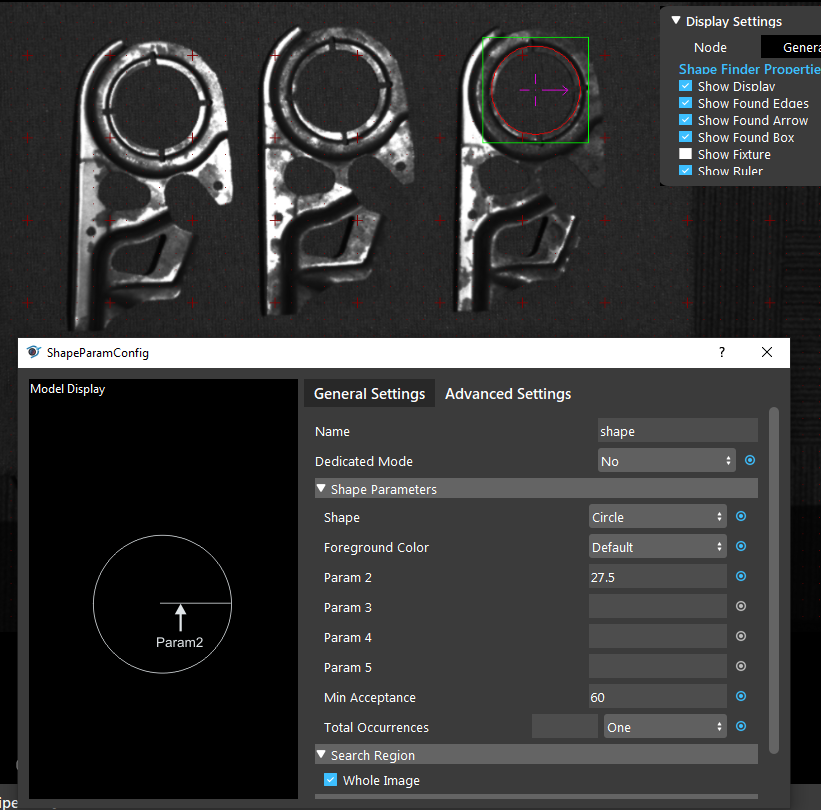
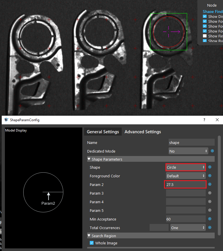
1. As shown in the image below, you are required to find the picking spot which is the center of the biggest whole, which by measure, you find that the diameter is 55mm. How should you configure your model to find.
create a model and use ring as shape, and 27.5 as parameter2 and 30 as parameter3.
create a model and use ellipse as shape, and 30 as parameter2 and 27.5 as parameter3.
create a model and use defualt circle as shape, and enter 27.5 as parameter2.
create a model and use defualt circle as shape, and enter 55 as parameter2.
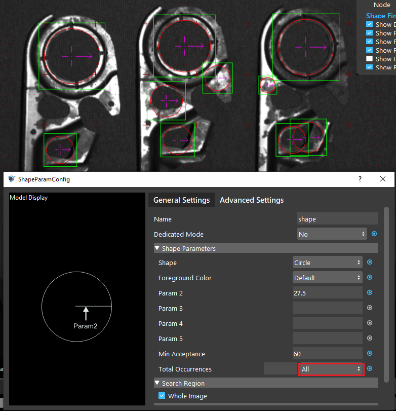
- As the image below, you are only detecting one object at the moment, how do you change the settings to detect all 3 targets in the image.
Change Dedicated Mode to Yes.
Change Min Acceptance from 60 to 40.
Change Foreground Color to any.
Change Total Occurrences to All.
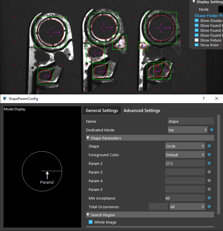
- As the image below, you are finding more shapes than you are hoping for. How should you tune the settings to find only the biggest circles.
Change Min Acceptance from 60 to 88.
Change Dedicated Mode to Yes.
Change Foreground Color to any.
Change Advanced Settings -> Certainly to 100.
Answers for Excercises
Answer: C
Explanation: Since the hole is in circluar shape, the simplest way is to use circle as shape, and that parameter2 takes radius in milimeters as input.
Answer: D
Explanation: The Total occurrence determines how many object the algorithm will find before terminatation by timeout.
Answer: A
Explanation: Min Acceptance determines the minimum matching score where an occurrence is accpeted, raising it will eliminate the less accurate results (smaller circles).
