Qualitative calibration validation
Attention
This validation method relies on a human operator visually confirming the correctness of a calibration, hence is a coarse check.
DaoAI also allows to perform a Quantitative calibration validation, which is more accurate, and recommended for applications that need to keep an eye on sources of picking errors.
Quantitative validate the result means we are projecting back some known objects back to the cloud, and compare it with what we actually see from the camera. Following are general steps:
Collect validating bag data
Config the flowchart, and run dedicated flowchart to check the visual result
Collect validating bag data
Open the same workspace for running the calibration, and set the robot pose to different ones, and collect a group of validating data. Refer to Collect calibration bag files or Collect sphere calibration bag files for more details about collecting data.
Tip
for validating data, save the bag files into “Data\Validation” folder will save you some time in future steps.
Circle Board Calibration Validation
Gripper visulization - Eye-to-hand only
The first step is to load the testing bag file into the Reader node.
In the Calibration node, you need to type in the yml file name stored in the calibrations folder under the current workspace folder. For details of the location refer to Circle Board Output File
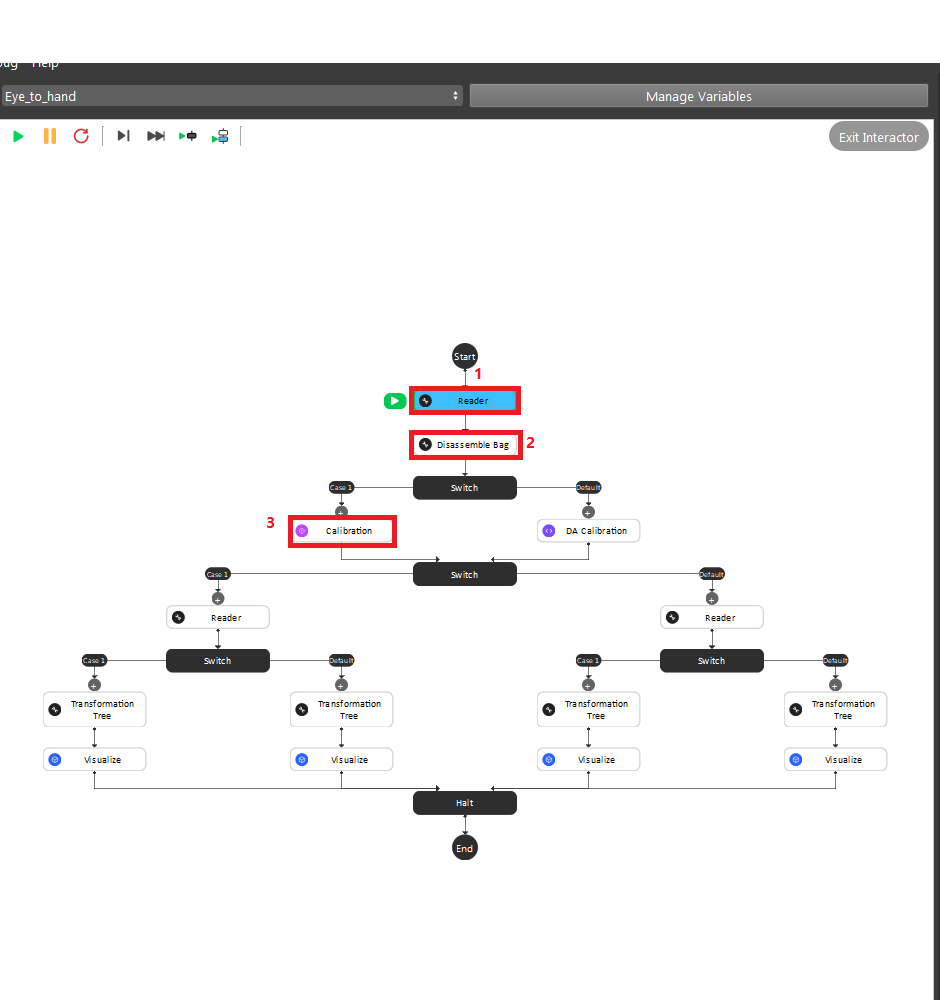
After the second switch, you need to load the gripper model they want to use based on the validation approach they chose in the beginning.
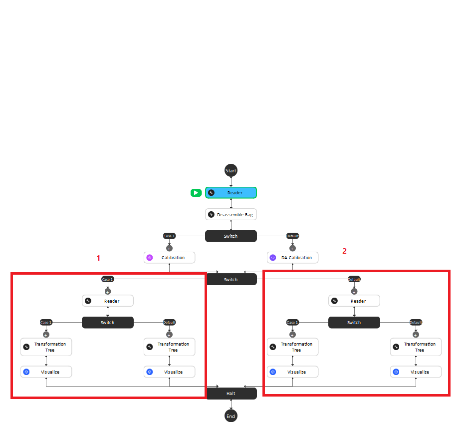
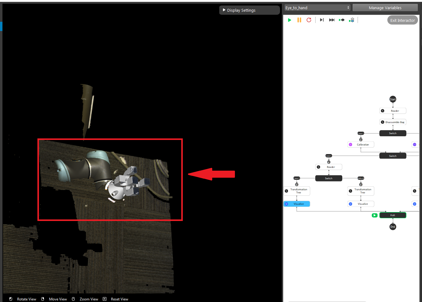
The left sub-child path is to visualize how well the gripper model matches the gripper’s cloud.
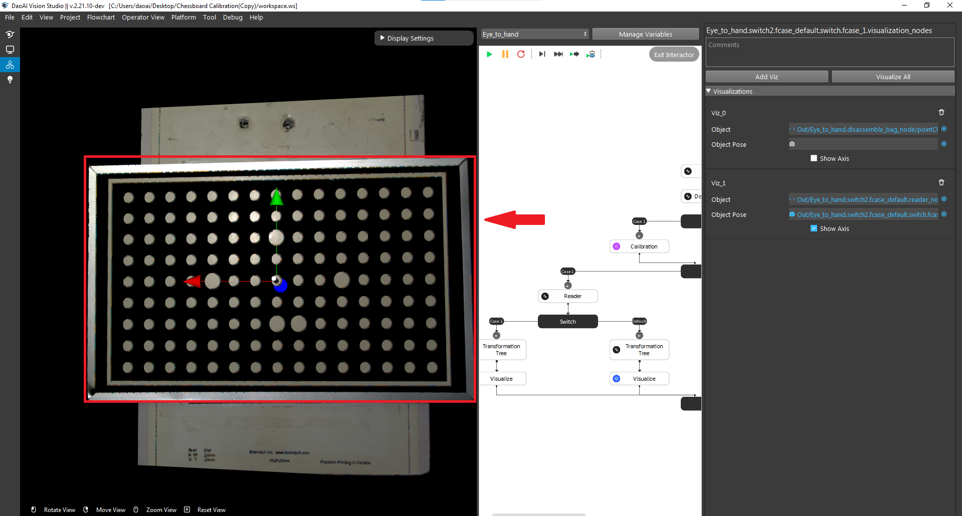
Pin visualization - Eye-to-hand
The right sub-child path is to visualize how good the world is located in the cloud. (The pen should plug right in the center of the first circle of the chessboard.) (Small circle) or check if the pen is located in the center of the central circle of the board. (Large circle)
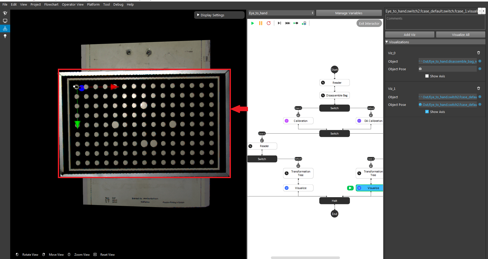
Attention
The testing bag file cannot be the same as the one used for generating the yml file. You need to readjust the poses and check the result using multiple bag files with different orientations.
Pin visualization - Eye-in-hand
Use the first and second Readers to load the gripper model ply file and the bag file respectively. Then, click the Calibration node and enter the yml file name that you want to validate.
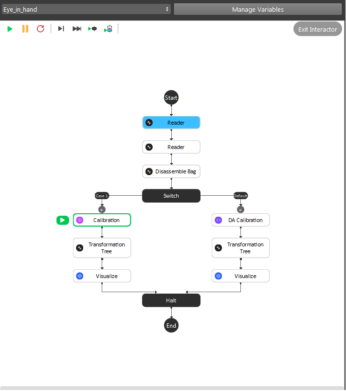
Different from the Eye To Hand flowchart, you can only validate the result by using the world in cloud method.
For Small circle, the pen(world) should be located at the center of the upper-left circle on the calibration borad.
For Large circle, the pen(world) should be located at the center of the calibration board.
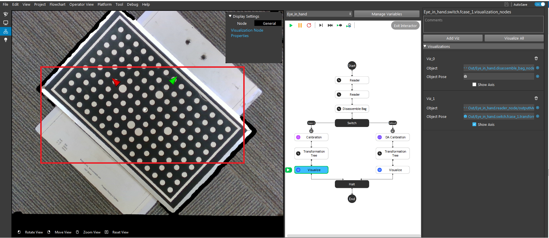
Attention
The testing bag file cannot be the same as the one used for generating the yml file. You need to readjust the poses and check the result using multiple bag files with different orientations.
Sphere visualization
For sphere calibration, there’s only one way of validation and it combined both eye-to-hand and eye-in-hand.
Go to the Validation flowchart in Sphere calibrations workspace. You will need to setup the first three nodes.
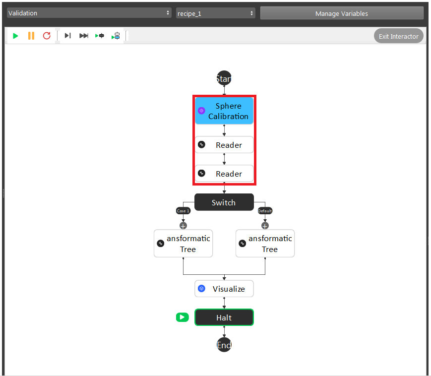
Sphere Calibration Node: enter the yml file name which you want to validate.
First Reader Node: Browse the bag data captured for validation, if you already saved them in Data/Validation folder of current workspace, then you don’t need to select again.
Second Reader Node: Browse the CAD model for you sphere, there are two existing models for 40mm and 60mm diameter in the Data folder.
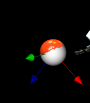
After setting up, you can click Visualize node and check how good the sphere CAD model matchs the sphere in point cloud. Sometimes you might need to move to different views on the display to judge the validation result.
Invalid robot-camera calibration?
If the outcome of calibration validation is that the current calibration is invalid, the most likely cause is that the camera moved with respect to the robot base (Eye to Hand) or robot flange (Eye In Hand). When this is the case, robot-camera calibration needs to be performed again.
If the camera has not moved with respect to the robot, it could be that something went unexpectedly wrong during calibration. The following pointers can help you identify the cause:
After capturing, the calibration plate moved before sending the current pose.
The calibration poses don’t comply with the requirement.
If you are integrating a new robot brand with DaoAI Vision, there might be an incompatability in the way poses are communicated between DaoAI Vision and the robot.
Note
If you are having trouble with robot-camera calibration, contact our support team.