3D Transformation Tutorial
When reading this page, we assume you have understood the 3D Transformation Concept
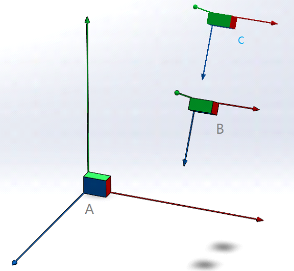
There are three objects, A/B/C. A sits on the world origin. Known that:
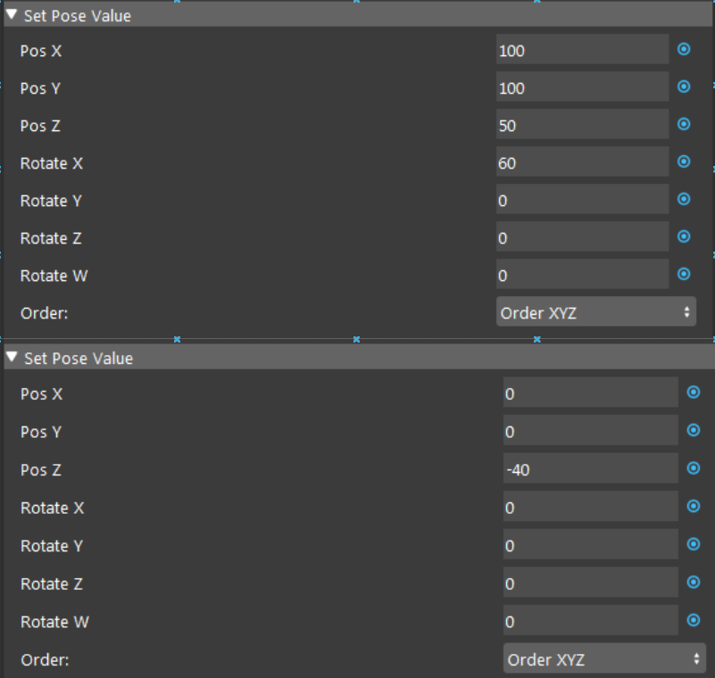
[B in A] = [100, 100, 50, 60, 0, 0]
[C in B] = [0, 0, -40, 0, 0, 0]
Acquire [C in World] from a transformation tree node.
Procedure
Follow the detailed procedure and work on your end as well.
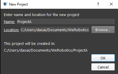
Open the software shortcut on desktop: WeRobotics EN/CN, and click New Project button.
Customize the project name and path, then click OK.
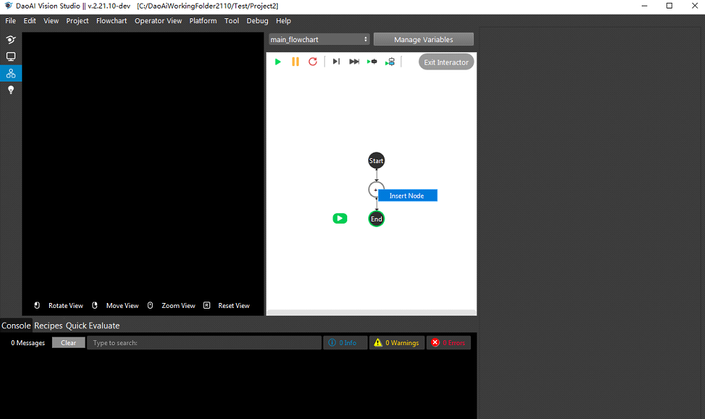
Right click on the +, and click insert node.
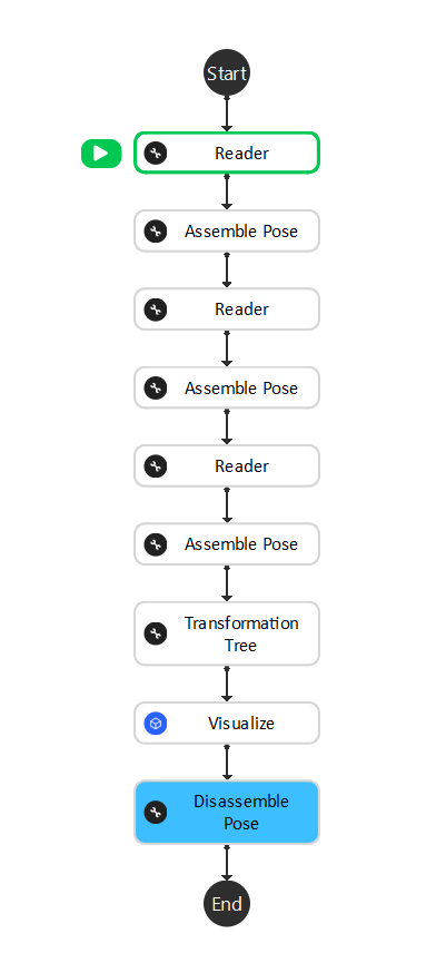
Insert the following nodes in the right order.
Download example Cubes CAD model, and left click on the first reader node. Click Browse button on the right and select Cube 20mmA.ply.
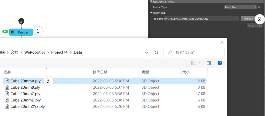
For the second and third reader nodes, repeats previous step and load Cube 20mmB.ply and Cube 20mmC.ply
Now since we want to make the Cube A sitting on the world origin, we leave the first Assemble Pose node with all values 0, which is [A in World].
For the second and third Assemble Pose node, configure them as below, which is [B in A] and [C in B].
The next step is to configure Transformation Tree node. Click Transformation Tree node and in the config page, click Set Input. This window should popup.
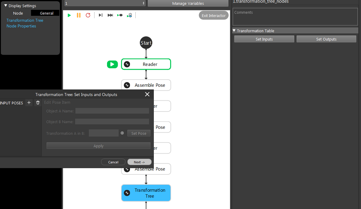
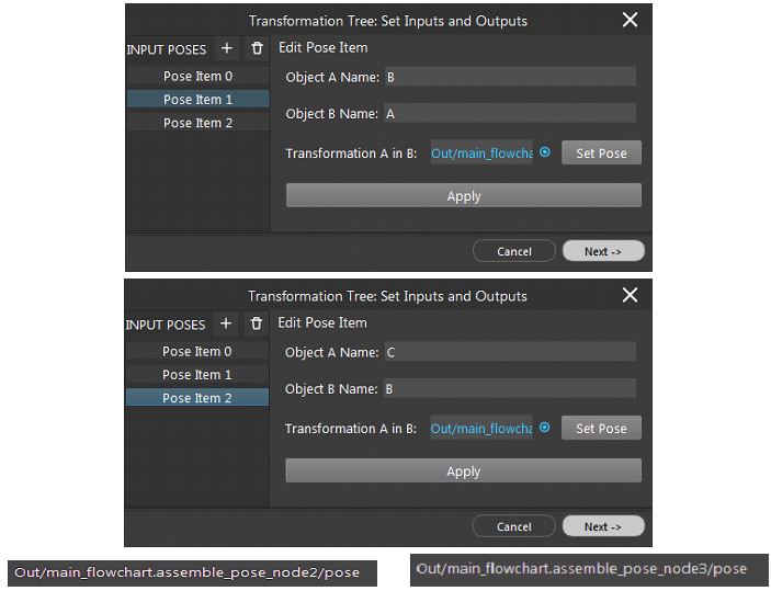
Click on the + button three times to create three inputs. Configure them as follows. For example, if entering [X in Y], X will be the object A name, and Y should be the Object B name. Then use the blue circle to link expression.
[A in World], link first Assemble Pose node.[B in A], link second Assemble Pose node.[C in B], link third Assemble Pose node.
First enter the names A and World. Then click the blue circle to open link expression window.
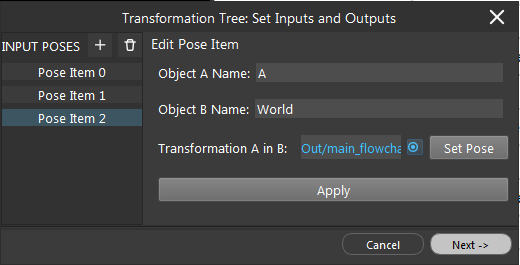
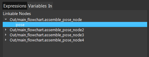
Search for “assemble”, and expand the assemble_pose_node. Then click the poses from dropdown list. Click Apply button before moving to net input.
Repeats previous steps for the next two inputs. When finished all three input configurations, click Next button.
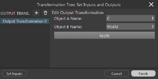
Select the output from dropdown list to be [C in World]
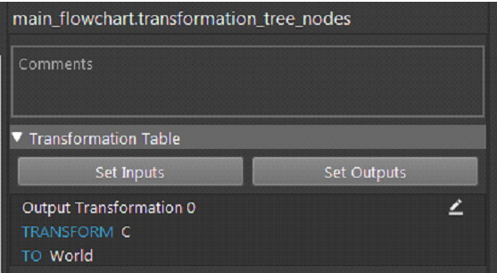
Now the output list is shown in config page, and [C in World] will be the 0-indexed item in the output array(Occurrence[0])
Click on the transformation tree node, and click Run to Selected Node button in the Operation List.

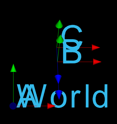
If the links and setup are correct, the result display should look similar to this. Use mouse to drag to see the transformation in different view points.
The next step is to add visualizations. Click Visualize node and in the config page, click Add button three times.

Link the objects to three Reader nodes, and link the Object Poses to 1. First Assemble Pose node, which is [A in World], 2. Second Assemble Pose node, which is [B in A]. Since A and World has 0 transformation, [B in A] = [B in World].
Warning
All Object Poses need to have same reference coordinate. In the form of [A in X], [B in X], [C in X]. X do not have to be the same name, but must have the same pose.
Object should link to the Reader.Output_Mesh since the readers are loading Mesh models.
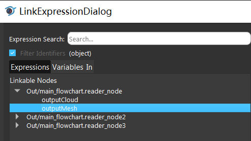
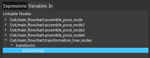
For the third Object Pose link, [C in World] is needed and it is generated by Transformation Tree node. So link it to the Transformation Tree output.
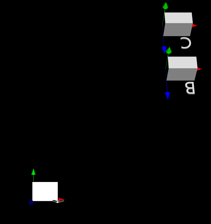
Click the Visualize node and run selected step. Check if the result is expected as image shown below.
The next step is to use Disassemble Pose node. Configure the node as following image shows. Then click on the node and run selected step.
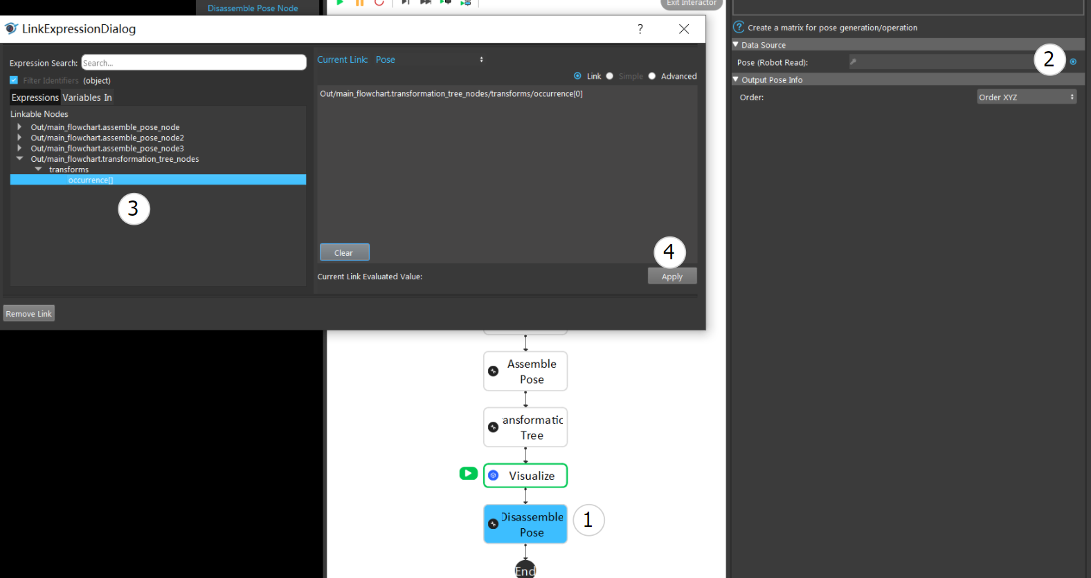
The expected result should be:

Further Question
What if we want to only gather the X and Y of this pose, and ignoring z and rotation?
Add an Assemble Pose node after Disassemble Pose node.
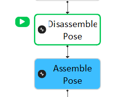
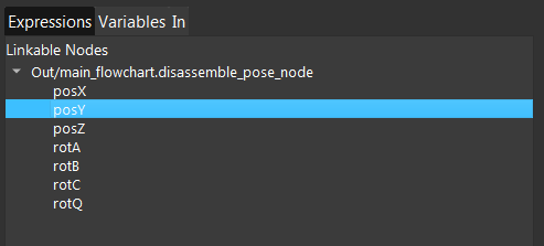
Since Disassemble Pose node will split the pose object into: Position X/Y/Z, Rotation X/Y/Z, etc. We can link only to the PosX and PosY output from it.
Add another Disassemble Pose node at the end, and check if the assembled result is correct.

