You're reading the documentation for a development version. For the latest released version, please have a look at master.
Reconstruct Node
Overview
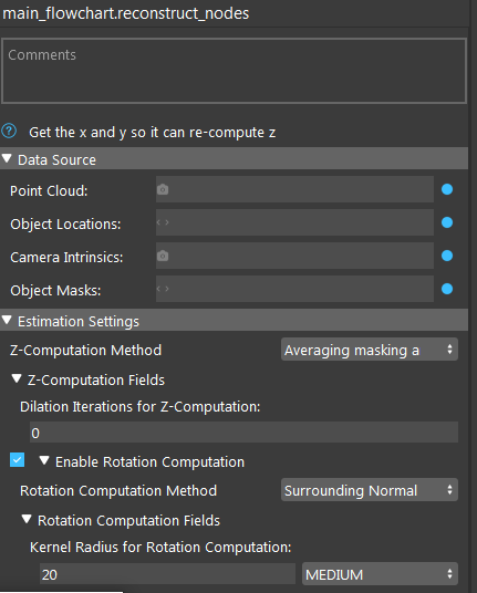
Input and Output
Input |
Type |
Description |
|---|---|---|
Point Cloud |
Point Cloud |
The Point Cloud from scene (camera, reader etc.). |
Object Locations |
Vec<Pose2D> |
The results of 2D poses. Usually from Mod Finder, Shape Finder etc. |
Camera Intrinsics |
CameraIntrinsic |
Camera Intrinsic from Camera node, used in computation. |
Object Masks (Optional) |
VecImage |
Detected model/shape masks from Mod Finder, Shape Finder or DL Segment nodes. Used only when the masks are used for rotation or Z computation. |
Output |
Type |
Description |
|---|---|---|
objectPositions |
Vector<Pose> |
Vector of 3D poses generated from “Object Locations” (2D poses). |
object_positions/size |
int |
Number of object positions. |
success |
bool |
Whether the reconstruct process of all pose is successful. |
Node Settings
Data Source
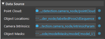
Point Cloud
The Point Cloud from scene(camera, reader etc.)
Object Locations
The results of 2D poses, usually from Mod Finder, Shape Finder, or DL Segment node.
Camera Intrinsic
Camera Intrinsic from Camera node, used in computation.
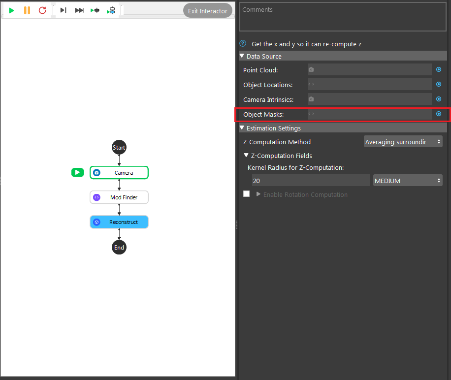
- Object Masks
Detected model/shape masks from Mod Finder, Shape Finder or DL Segment nodes. Used only when the masks are used for rotation or Z computation. This is an optional setting for Reconstruct node. You can leave it empty if not needed.
Estimation Setting
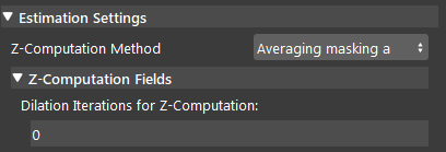
- Z-Computation Method:
This field is the options for computation of Z-value: Averaging surrounding points, and Averaging masking area.

The node has two ways of constructing Z-value in 3D poses:
- Averaging Surrounding Points:
This is the default method which uses a set of surrounding points (square kernel) around the reference point and converts them to a point cloud (using the input point cloud) and takes the average Z value of the corresponding 3D points in the point cloud. The size (radius) of the kernel can also be defined by the user. Using a bigger kernel will result in using more surrounding points for Z computation.

- Averaging masking area:
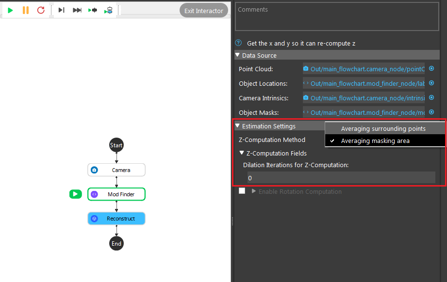
This method uses the mask obtained from Mod Finder , Shape Finder, or DL Segment to obtain the Z value by using the non-zero pixels in the mask (model mask, shape mask or segment mask depending on which node you are using before reconstruct node) and taking the average Z value of their corresponding points in the point cloud. There is also a dilation iterations parameter that can be used to dilate the model/shape mask if needed. More dilation results in using more points for Z computation.
Enable Rotation computation
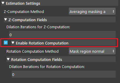
If this option is checked by the user, the program will compute the rotation of the object with respect to the camera coordinates system. The nodes has two ways of constructing rotation: Surrounding Normal Points and Mask Region Normal.
- Surrounding Normal Points:
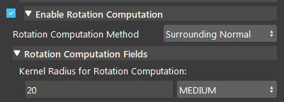
This is the default method which uses a set of surrounding points of the reference point to fit a plane in the point cloud and then, uses this plane to find normal vector which is then used for rotation calculation. However, this method can fail if the surrounding points are nan (invalid), especially in cases that the target shape / model is a hole. However, you can control the kernel used around the reference point by changing Kernal Radius for Rotation Computation to fit the plane and calculate the rotation.
- Kernal Radius for Rotation Computation (Default: MEDIUM):
The radius of kernel used to compute rotational value. A large value uses more points to fit a plane and find the normal at the reference point.
- Mask Region Normal:
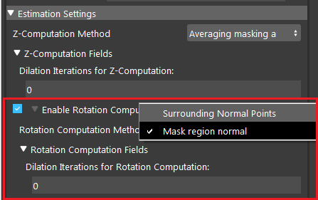
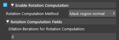
This method uses the mask/masks obtained from Mod Finder, Shape Finder, or DL Segment node and converts it to a cloud to obtain the Rotation value by using the non-zero pixels in the mask and fitting a plane to the corresponding 3D points. Then, the normal of the plane estimated which is used for rotation calculation. There is also a dilation iterations that can be used to dilate the model/shape/segment mask if needed. This option is especially good for cases that we have detected a shape/model which is actually a hole. In this scenario, most of the cases, the reference point and the surrounding points are nan. Therefore, using the surrounding points is not able to find the normal (unless a big kernel size is used), but using the mask region will use the mask to fit the plane and ignore the nan points.
- Dilation Iterations for Rotation Computation (Default: 0):
The number of dilation iterations to perform. This can be used when we want the mask to use more points for R computation. More dilation results in using more points for plane fitting and rotation calculation.
Procedure of Using Reconstruct Node
- Open a workspace in DaoAI Vision Studio.
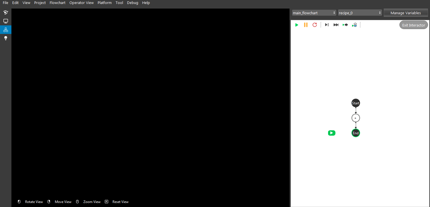
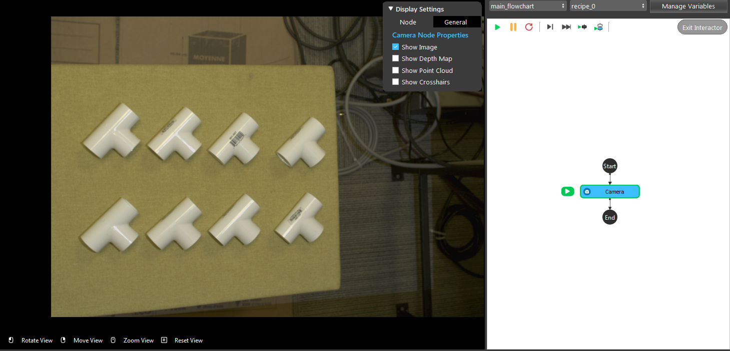
- Insert a Camera node to get the source image.
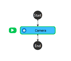
- A virtual image is used to demonstrate. Refer to the Camera Node page for tutorials on how to connect to camera.
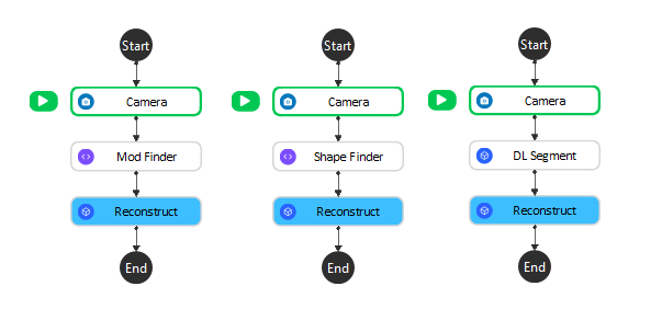
- Insert a Mod Finder node, Shape Finder or DL Segment node to find the T tube. Mod Finder node is used for demonstration here.
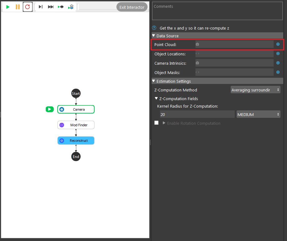
- Click on the blue dot on the right side of “Point Cloud” to link the point cloud from the camera node above as input.
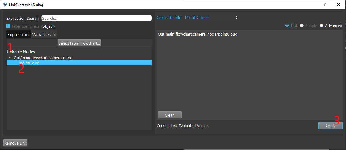
- Expand the “Out/main_flowchart.camera_node” on the left window of the LinkExpressionDialog. Click the “image” then Apply.
- Click on the blue dot on the right side of “Object Locations” to link the 2D poses from the Mod Finder, Shape Finder or DL Segment node above as input.
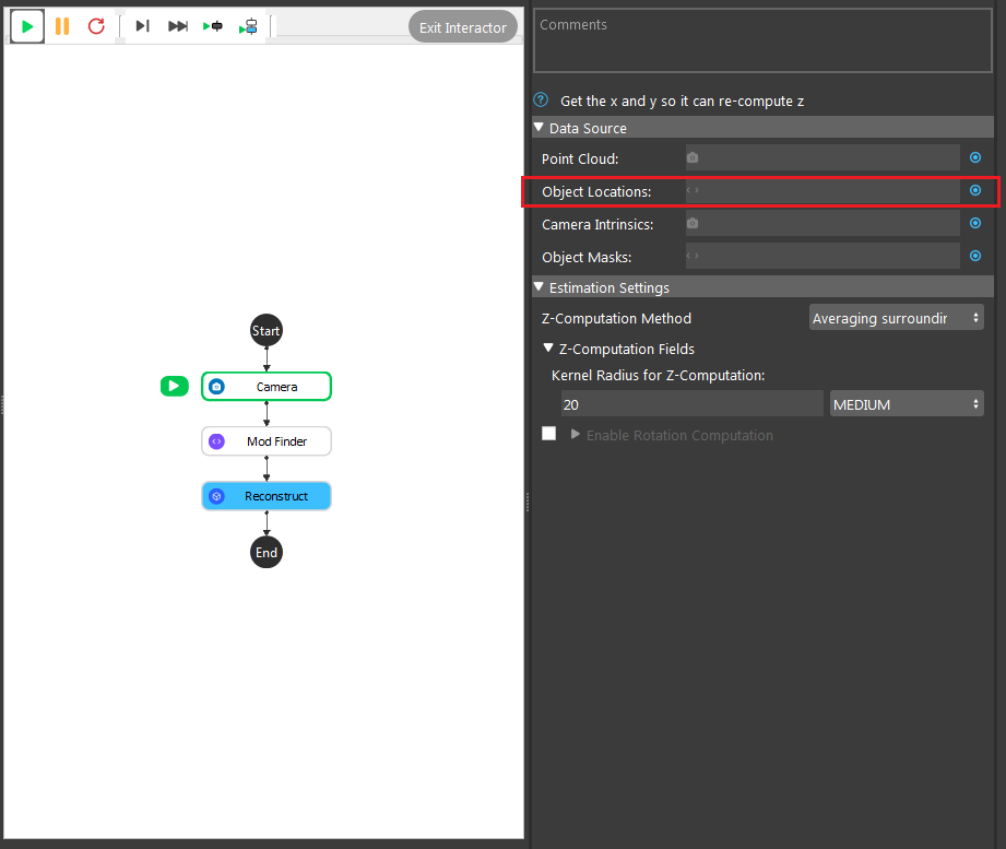
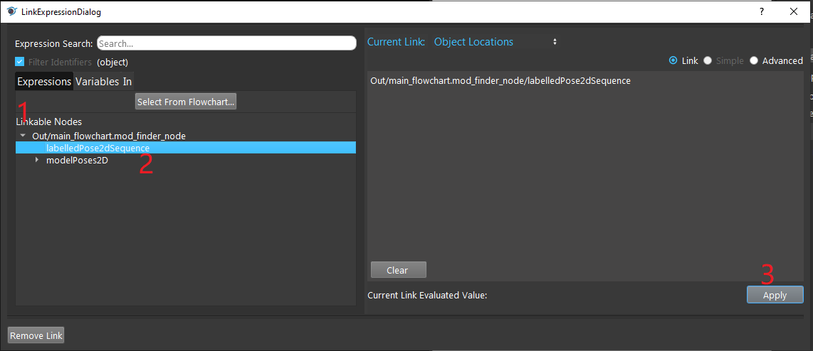
- Expand the “Out/main_flowchart.mod_finder_node” on the left window of the LinkExpressionDialog. Click the “labelledPose2dSequence” then Apply. Input “labelledPose2dSequence” referring to all the occurrences of all models. Based on your need, you can choose “modelPoses2D” and fill in the model you want to refer as well.
- Click on the blue dot on the right side of “Camera Intrinsic” to link the camera intrinsic data from the camera node above as input.
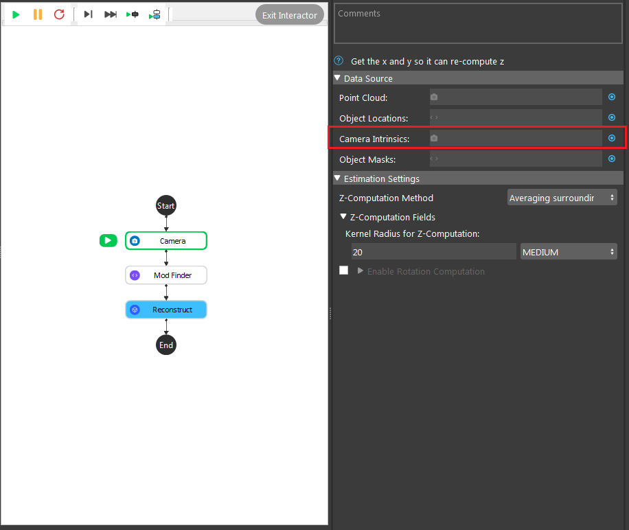
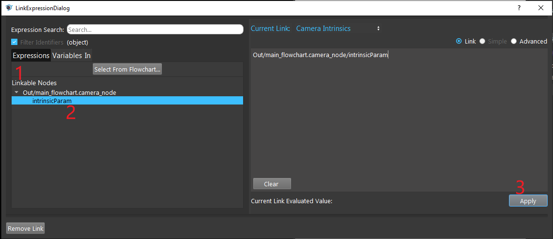
- Expand the “Out/main_flowchart.camera_node” on the left window of the LinkExpressionDialog. Click the “intrinsicParam” then Apply.
- Click on the blue dot on the right side of “Object Masks” to link the object masks from the Mod Finder, Shape Finder or DL Segment node above as input.
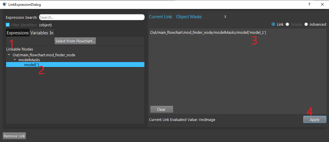
- Expand the “Out/main_flowchart.mod_finder_node” on the left window of the LinkExpressionDialog. Click the “modelMasks/model[‘’]” then fill in “model_x”(the model you want to refer) and Apply.
- Choosing the suitable method for Z-computation according to the requirements.
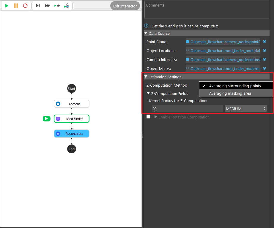
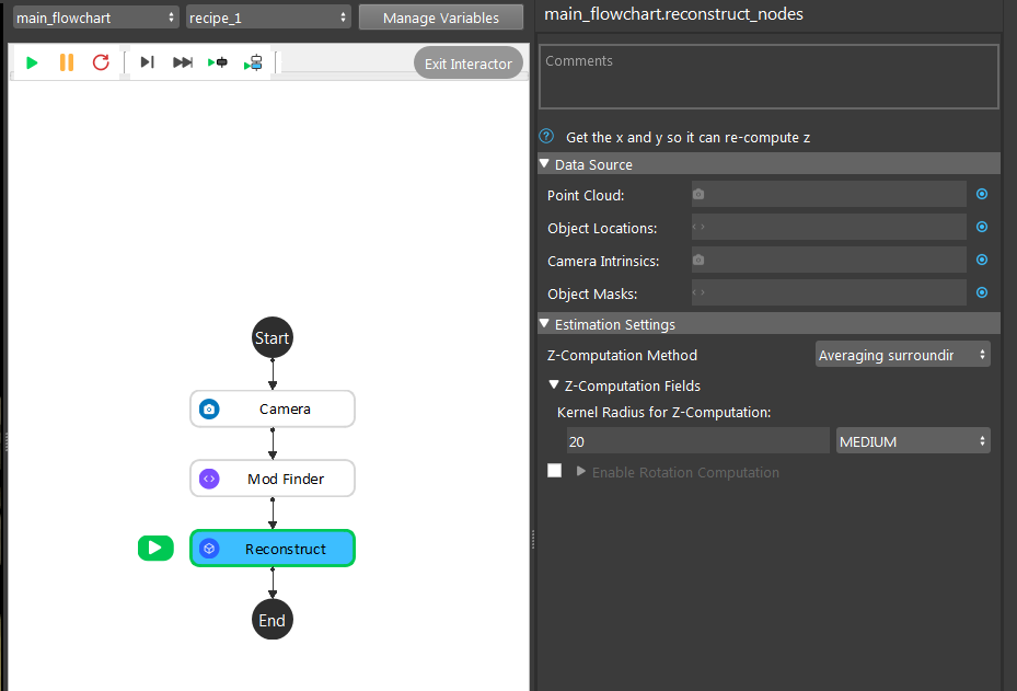
Averaging surrounding point uses the algorithm to calculate the Z-direction from the average of all the surrounding points. In the image shown above, 20 is the radius which from the center point, 20 pixels surrounding points will be used for this calculation.
Averaging masking area uses the algorithm to to calculate the Z-direction from the average of all the points on the model mask. In the image shown above, 0 is the number of dilation iterations used to perform dilation operation on the mask. This can be used when you want the mask to use more points for Z computation.
- Choosing the suitable method for Z-rotation computation according to the requirements.
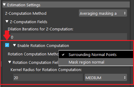
Surrounding Normal Points uses the algorithm to to calculate the Z-rotation from all the surrounding points. In the image shown above, 20 is the radius which from the center point, 20 pixels surrounding points will be used for this calculation.
Mask Region Normal uses the algorithm to to calculate the Z-rotation from the average of all the points on the model mask. In the image shown above, 0 is the number of dilation iterations used to perform dilation operation on the mask. This can be used when you want the mask to use more points for Z-rotation.
Note
All the points which are used for calculation are VALID. Invalid points will be neglected. Therefore, if your kernel set to a small number, and there are lots of invalid points around your center, the result might be bad. Try increasing the kernel radius.
- Run the Reconstruct node, you can see that all the 2D poses detected from Mod Finder node are now becoming 3D poses.
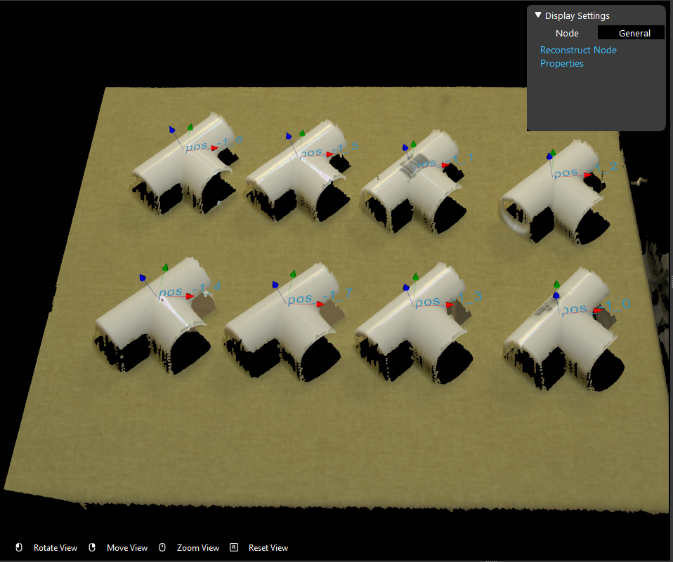
Exercise
Try to come up with the setting on Reconstruct node according to the requirements below. You can work on these exercise with the help of this article. We also have answers attached at the end of this exercise.
This is some helpful resource when you are working on the exercise: dcf files and pt files.
Scenario 1
We have a project for large mechanical parts company automation. The company wants the robot to pick these part box from the conveyor bell.
Image above is the box on the conveyor bell. We have the all the hardware setup, and the detection flowchart uses Mod Finder node and Reconstruct node. Now we are stuck on the setting of Reconstruct node. Please choose the one correct answer from the options:
Shown in the image above, we have the Reconstruct node inserted in the flowchart. How do you add inputs for these settings?
Right click on the Reconstruct node and you will see the option for adding inputs;
Click on the empty spot on the grey rectangle next to Point Cloud, for point cloud inputs;
Click on the blue dot next to Point Cloud, for point cloud inputs;
Click on the green triangle and choose the inputs for Reconstruct node;
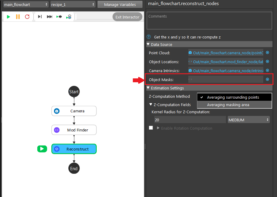
Can you leave this setting empty with the current setup?
Yes, it will output the expected result;
Yes, you can leave it empty but it will have warning to remind you the Object Masks input is empty;
Yes, you can leave it empty but it will have warning to remind you cannot compute the result with the input empty;
No, it will show you error which this input cannot be empty;

No restriction is applied to pick and drop the box. Which means you can pick this box in any position with any angles, can you use the setting above?
Yes;
No;
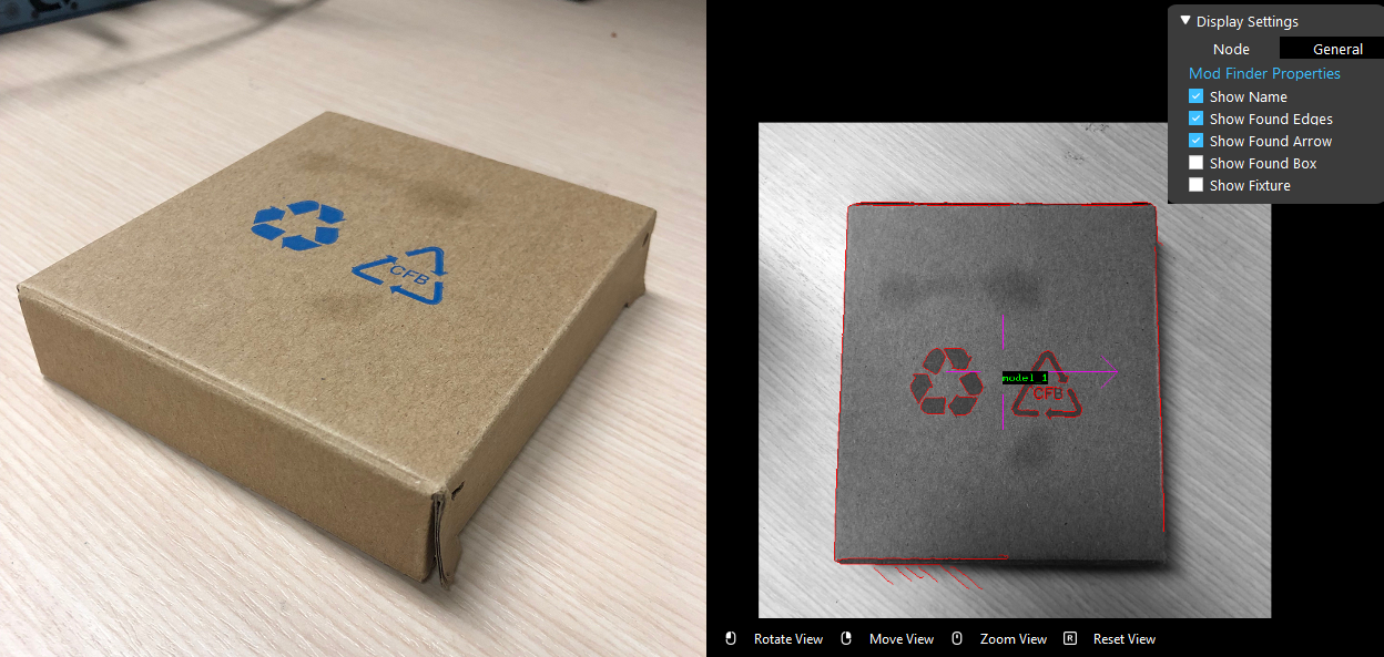
Now, you have a new requirement from your customer. They want to pick the box with the writing facing upward. You have Mod Finder node setup, and you are wondering: will the X, Y direction of 3D poses from Reconstruct node remains the same? Hints: you should try this on Vision studio to verify your thought.
Yes;
No;
Which Z-computation method is better for this object?
Averaging surrounding points;
Averaging masking area;
Both methods work fine for this object;
Scenario 2
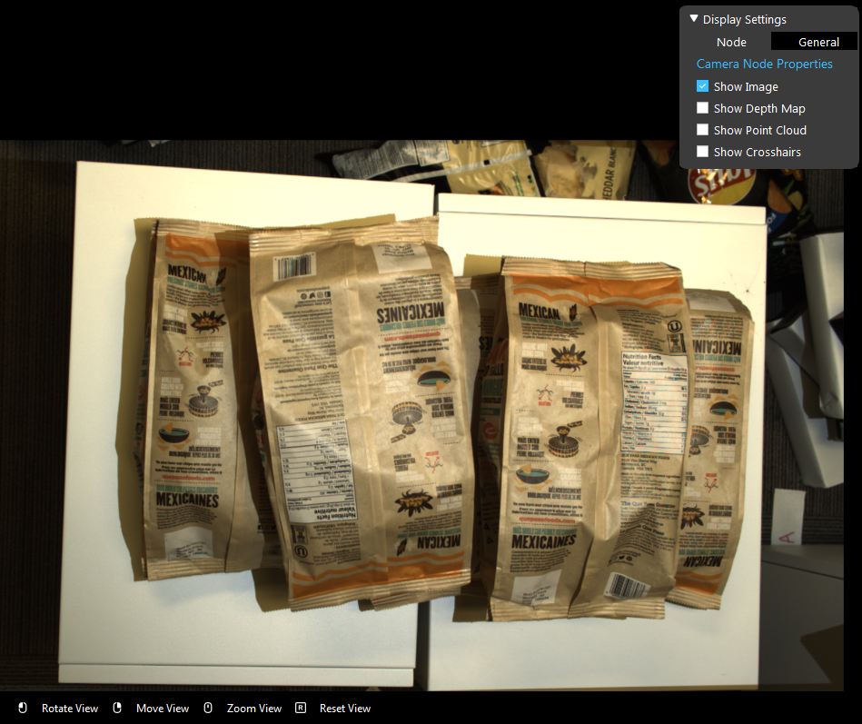
We have a project for Chips manufacture automation. The company wants the robot to pick these bags of chips from the pallet.
Image above is the chips on the pallet. We have the all the hardware setup, and the detection flowchart uses DL Segment node and Reconstruct node. Now we are stuck on the setting of Reconstruct node. Please choose the one correct answer from the options:
Tip
You might want to use Vision studio to test and try out your options for this scenario.
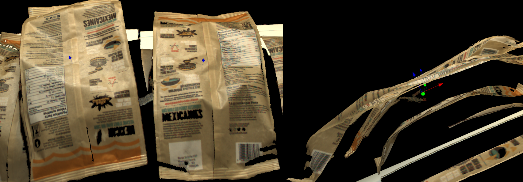
Shown in the image above, which method is used for this result? And how would you change the input in order to change the pose to the surface of the bag?
Averaging surrounding points, change the kernel radius for z-computation to Large;
Averaging surrounding points, change the z-computation method to Averaging masking area;
Averaging masking area, change the z-computation method to Averaging surrounding points;
Averaging masking area, increase the dilation iterations for z-computation to to around 10 to 20;
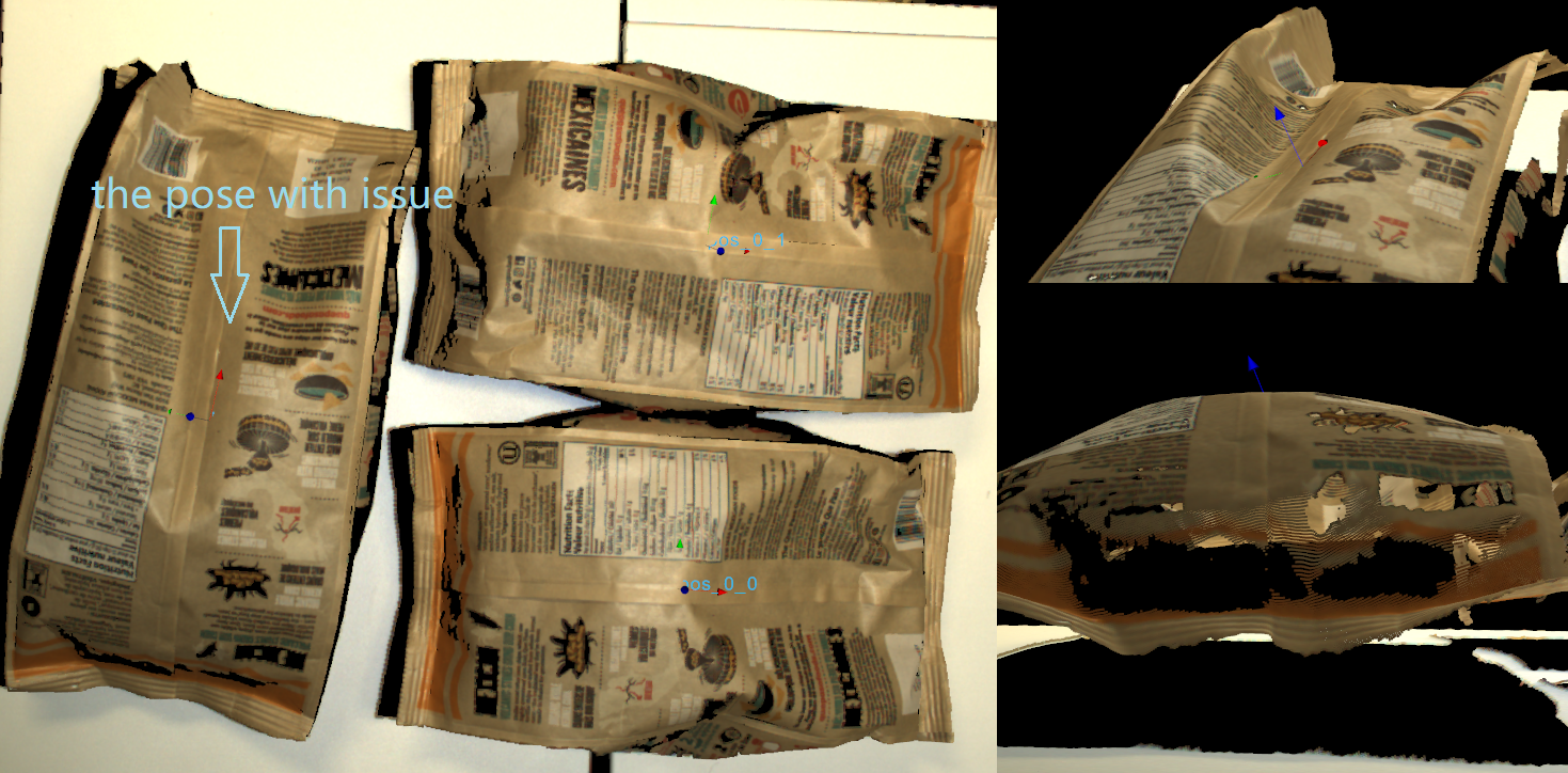
There is a new requirement come in, customer wants the robot to pick the chips with a pose which as perpendicular to the table as it could. Therefore, the 3D poses from Reconstruct node should point to upward. However, you observe that the left chip’s Z direction is not so upward straight. Which Z-rotation method is probably applied here? And how would you change this to get the expected result?
The image uses the Surround Normal Points for Z-rotation with kernel radius Large; change the kernel radius for Z-rotation to Small in order to fix it;
The image uses the Surround Normal Points for Z-rotation with kernel radius Large; change the Z-rotation method to Mask Region Normal and dilation iterations to 1 in order to fix it;
The image uses the Mask Region Normal for Z-rotation with dilation iterations 0; change the Z-rotation method to Surround Normal Points and kernel radius to Small in order to fix it;
The image uses the Mask Region Normal for Z-rotation with dilation iterations 0; change the Z-rotation method to Mask Region Normal and dilation iterations to 1 in order to fix it;
Answers for Exercises
Scenario 1
C
Explanation: The blue dot is where you should click for inputs!
A
Explanation: You can leave the input Object Masks empty with Averaging surrounding points Z-computation method, since this method does not require the mask for its calculation, no errors and warnings will be displayed.
A
Explanation: Yes! And because the box has smooth surface and no angle restrictions applied, you do not need the Z-rotation computation here.
A
Explanation: Reconstruct node will not change the X, Y direction from their 2D poses.
C
Explanation: From all the information above, you can see there is no restrictions on the picking angle; also, Mod Finder node shows the reference point of this object is in the central of the smooth surface. Therefore, you can use Averaging surrounding points for Z-Computation in this object. On the other hand, the box has smooth surface, Averaging masking area will work fine on it.
Scenario 2
C
Explanation: The pose origin falls inside the object, this is the result from Averaging masking area. Because the surface of the chip bag is uneven and has lots of height difference. That is because when calculating the Averaging masking area, these Z-values resulting the average is somewhere inside the chip bags. You can also think about it reversely: if you use the Averaging surrounding points method, the algorithm uses the valid points around the origin, therefore it will not be fallen inside the surface. And C: “change the z-computation method to Averaging surrounding points” is the correct solution for this scenario.
B
Explanation: The Z direction of this pose is almost perpendicular to its surface: there is a small flat area around the origin, therefore it is the result from Surround Normal Points, and the radius will not be too small. If you apply the Mask Region Normal, the algorithm uses all the points of this object, which will more likely to resulting a upward Z direction. You should definitely try out the answer in Vision studio for this exercise.
