You're reading the documentation for a development version. For the latest released version, please have a look at master.
Scene Crop Node
Overview
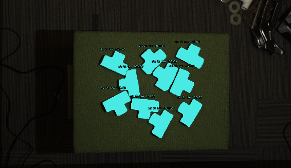
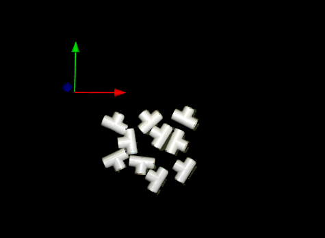
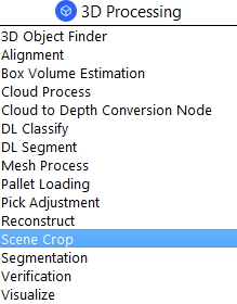
The Scene Crop Node uses segmentation results to crop a Point Cloud and output a vector of clouds corresponding to each segment.

Input and Output
Input |
Type |
Description |
|---|---|---|
Segment Results |
vector<Segm> |
Segmentation result of objects. Usually from DL Segment, Segmentation node. |
Scene Cloud |
pointCloud |
The scene point cloud to be cropped. Usually from Camera, Cloud Process node. |
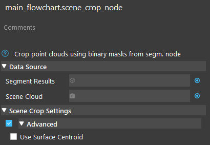
Use Surface Centroid |
bool |
Whether to compute the centroid of the segmented point cloud when computing segmentPoses. |
Output |
Type |
Description |
|---|---|---|
segmentClouds |
SVecCloud |
A vector of point cloud, representing the cropped point cloud for each segment. |
segmentPoses |
vector<Pose> |
Poses of each point cloud, if the scene cloud has normals (from cloud process node), this pose will represent the surface normal of the segment. |
Node Settings
Data Source

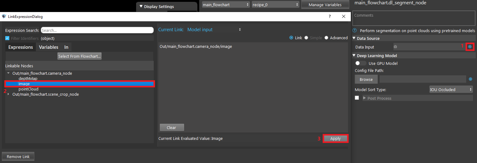
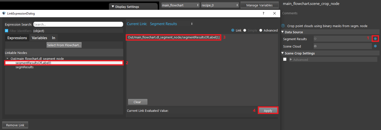
- Segment Results
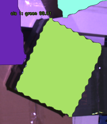
Segmentation result of objects. Usually from DL Segment, Segmentation node.
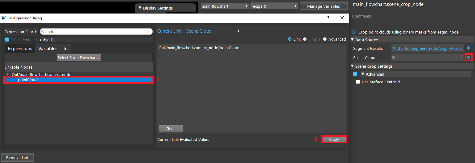
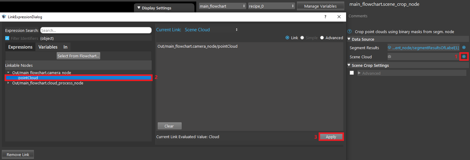
- Scene Cloud
3D point cloud representing the scene. Usually from Camera, Cloud Process node.
Scene Crop Settings

- Use Surface Centroid (Default: false)
Whether to compute the centroid of the segmented point cloud when computing segmentPoses.
Procedure to Use
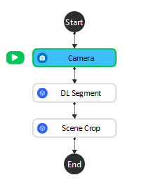
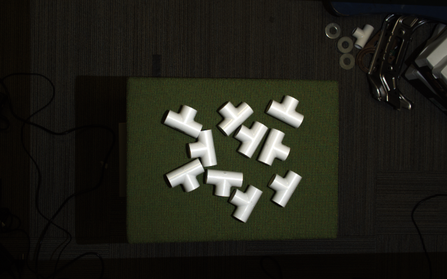
We will need a few more nodes to demonstrate Scene Crop node. Here are the files that you might need.
- Add a virtual camera with the daoai_0.dcf. See Camera Node for more detailed instructions.
Exercise
Here is the link to files .
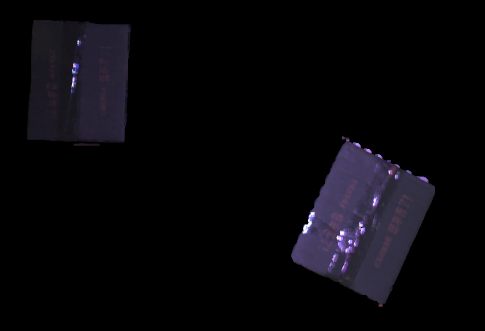
Try to crop out the two dark green boxes in the following scene.
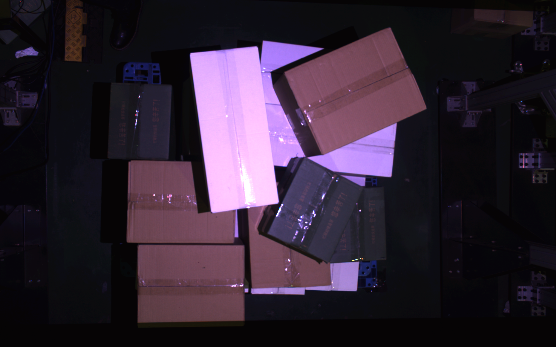
The flowchart should look the same as the one in Procedure to Use.
Answers for Exercise
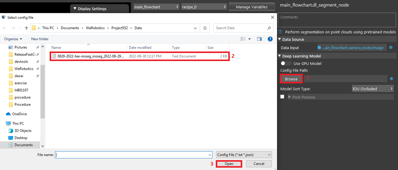
- Please refer to Procedure to Use for the Camera and DL Segment setup. They are very similar.

