You're reading the documentation for a development version. For the latest released version, please have a look at master.
Visualize Node
Overview
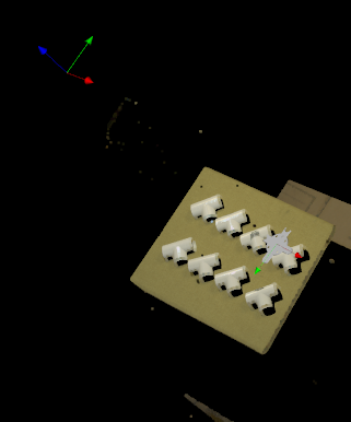
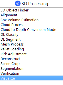
The Visualize node is a utility node that visualizes point clouds or meshes in the same coordinate system using their respective positions. It can also apply poses to objects before visualizing.
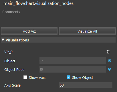

Input and Output
Input |
Type |
Description |
|---|---|---|
Object |
Point Cloud / Mesh |
The object to be visualized. |
Object Pose |
Pose |
The pose to be applied to the object (optional). |
Show Axis |
bool |
Whether to display the pose’s axis or not. |
Show Object |
bool |
Whether to display the object or not. |
Axis Scale |
int |
The size of the axis to be shown. |
The Visualize node has no output, it only uses the display.
Node Settings
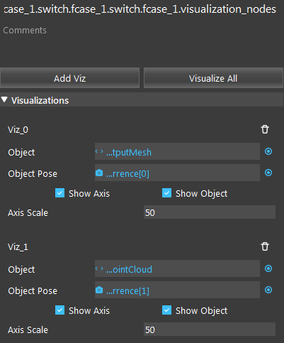
Visualizations
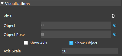
There can be an arbitrary number of visualization items.
- Object
The object to be visualized.
- Object Pose
The pose to be applied to the object (optional).
- Show Axis (Default: false)
Whether to display the pose’s axis or not.
- Show Object (Default: true)
Whether to display the object or not.
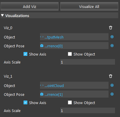
- Axis Scale (Range: [1,100]; Default: 50)
The size of the axis to be shown.
Procedure to Use
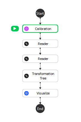
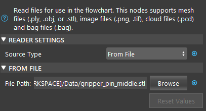
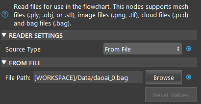
We will need a few more nodes to demonstrate the Visualize node. You can get the files here .
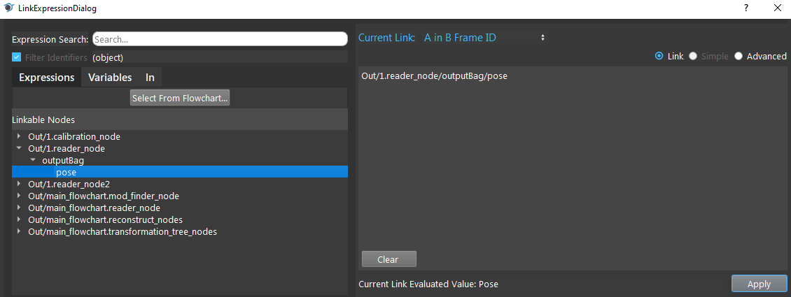
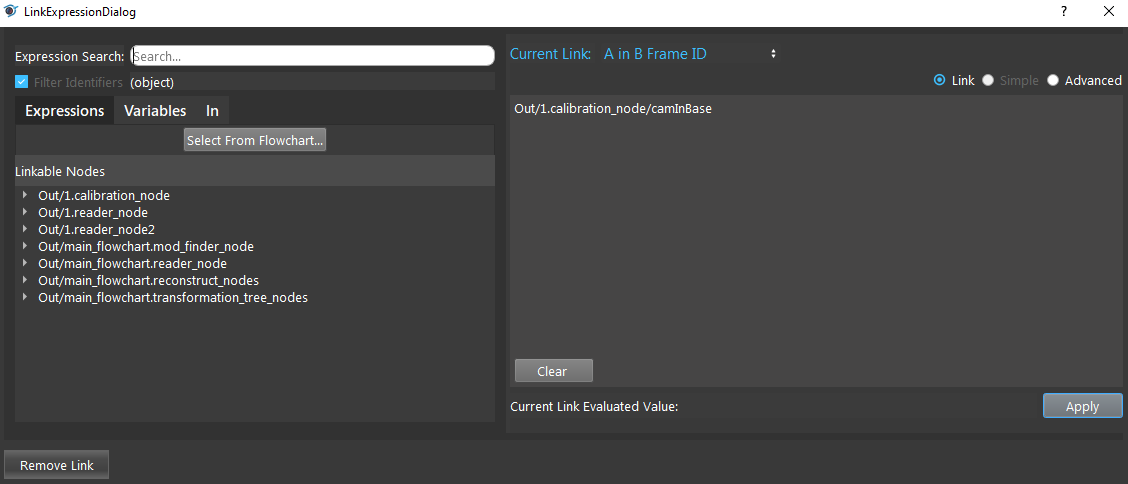
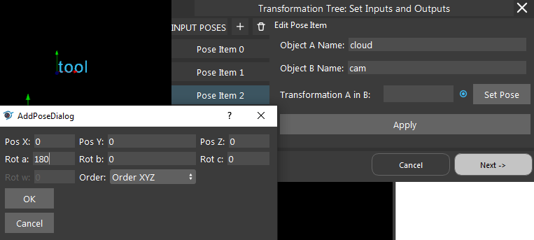
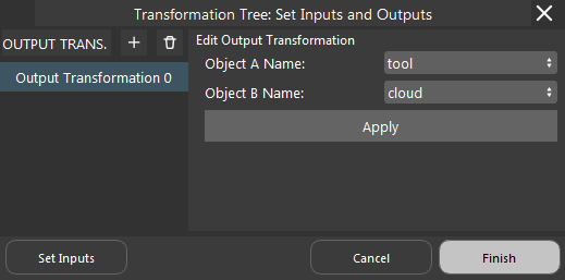
- In the Transformation Tree, we need the tool in cloud relation to visualize the gripper. Add a tool in base relation, and link the bag’s output pose; Add a cam in base relation, and link calibration’s camInBase output; Add a cam in cloud relation, click “Set Pose”, change Rot a to 180. Finally, add a tool in cloud output. Remember to click “Apply”.
Exercise
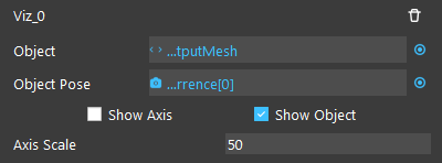
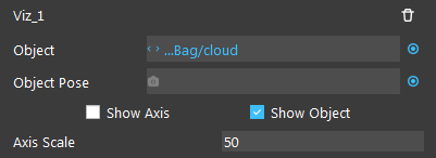
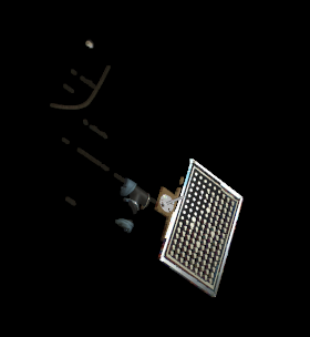
You have this flowchart and are trying to see the visualization of the scene with the gripper. However, when you click on the Visualize node, the display appears to be a black screen. How can you fix the problem, given the following visualizations settings and that the Object and Object Pose links are correct?

Answers for Exercise
